Assigning the wrong soldering process to a part leads to heat-damaged components, poor hole fill or slow manual rework on every board. Choose per part, not per board: reflow for surface-mount parts, pin-in-paste reflow for through-hole parts that tolerate the reflow profile, wave soldering for boards with many through-hole joints on an underside that can pass over a wave, selective soldering for a few heat-sensitive, hard-to-reach or heavy through-hole parts, and hand soldering for rework and one-offs.
This is a selection comparison based on public sources, not on our own tests. Reflow heats the whole assembly, so every part must tolerate the reflow conditions in its maker’s assembly specification; for moisture-sensitive surface-mount packages, that includes the IPC/JEDEC J-STD-020 classification temperature. Wave soldering applies flux and molten solder across the board’s underside. Selective soldering, in the words of a 2023 paper from contract manufacturer Plexus, combines the repeatability of a fully automated machine with the flexibility of hand soldering. When a board’s through-hole parts cannot join the reflow pass, choose wave, selective or hand soldering for them as a second process.
This page compares the four processes on the same decision factors, sets out where each one struggles, and gives a four-question method to assign a process to each part. Sources are papers from an equipment maker, a contract manufacturer and a flux maker, plus IPC’s profiling guideline contents; each is labelled where it is used.
| Input or item | Typical value or source | Why it matters |
|---|---|---|
| Part list split by mounting | Bill of materials: SMD or through-hole | Surface-mount parts default to reflow |
| Heat tolerance of each through-hole part | Part datasheet; J-STD-020 rating where given | Decides whether it can ride through reflow |
| Number and spread of through-hole joints | Assembly drawing | Many joints favour wave; a few favour selective |
| Parts on the underside | Assembly drawing | Limits what can pass over a wave |
| Thermal mass at the joints | Layer count, copper planes, heavy parts | Sets preheat needs and hole-fill difficulty |
| Acceptance requirements | IPC J-STD-001 and IPC-A-610 (J revisions announced April 2024), or the customer’s drawing | Defines what a good joint looks like |
How do the four soldering methods compare?
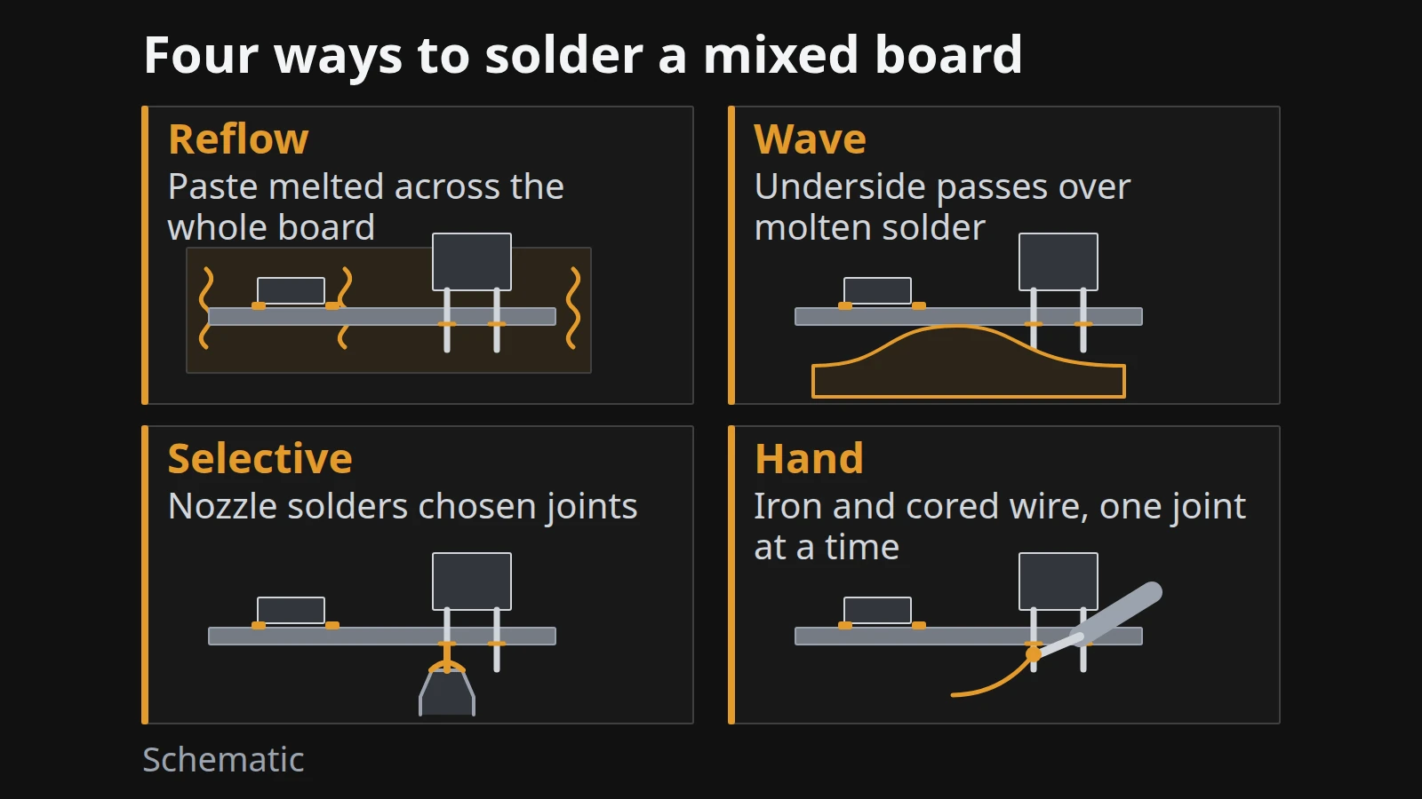
The four processes differ in how solder reaches the joint and how much of the board gets hot: reflow melts pre-printed solder paste across the whole assembly, wave floods the underside with molten solder, selective solders chosen joints with a nozzle or nozzle plate, and hand soldering heats one joint at a time with an iron and flux-cored wire.
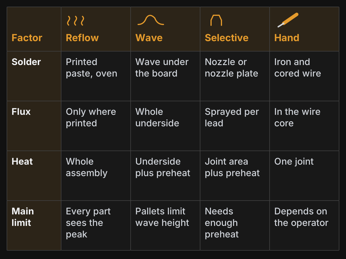
Figure 1. The four processes compared on the same factors. Based on the sources listed; not a test result.
| Factor | Reflow | Wave | Selective | Hand |
|---|---|---|---|---|
| How solder is applied | Paste printed on pads, melted in an oven | Board underside passes over a flowing wave | Mini-wave nozzle on a moving gantry, or a dip with a nozzle plate | Iron and flux-cored wire, joint by joint (the configuration compared here) |
| How flux is applied | Inside the paste, only where printed | Sprayed, foamed or waved across the whole underside | Sprayed onto each lead in a directed amount | In the wire core, for flux-cored wire |
| What gets hot | Whole assembly, to the reflow peak | Underside in contact with solder; whole board in preheat | Joint area plus preheat | One joint at a time |
| Typical parts | Surface-mount; suitable through-hole via pin-in-paste | Through-hole on boards designed for the wave | A few through-hole parts on mixed boards; heat-sensitive or hard-to-reach parts; heavy 3D assemblies | Rework, prototypes, parts no machine can reach |
| Main limit | Every part sees the reflow peak | Flux and solder reach the whole underside; pallets limit wave height | Needs enough preheat in the assembly; dip systems must control hole fill, bridging and solder balls | Repeatability depends on the operator |
| Source | J-STD-020; IPC-7530B contents | Shea et al.; Diepstraten (2023) | Shoaf et al. (Plexus, 2023); Diepstraten (2023) | Shoaf et al. (comparison with selective) |
None of the four is better in general; each wins for a particular kind of part. That is why the decision at the end of this page is made part by part. For how the reflow column’s heat limit is set, see our explainer on the J-STD-020 limits that cap a reflow profile.
Takeaway: Compare the processes on how solder, flux and heat reach each part; the right answer usually differs between parts on the same board.
What is wave soldering used for, and where does it struggle?
Wave soldering is used to solder through-hole leads in bulk: the board is fluxed, preheated, then carried across a wave of molten solder that wets the leads and fills the plated holes. It suits boards with many through-hole joints whose underside can be exposed to the wave, and it struggles where the underside is crowded, the parts are sensitive, or only a few joints need solder.
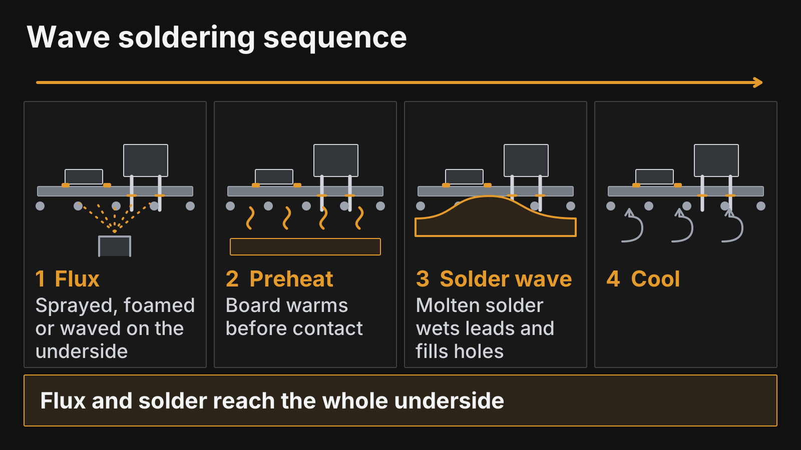
Figure 2. Wave soldering sequence. Flux and solder reach the whole underside, which is the source of most of its limits. Schematic.
Three limits come up in the sources:
- Flux everywhere underneath. Shea, Arora and Brown, writing for flux maker Alpha, note that wave flux is applied to the entire bottom side of the board, some reaches the top side, and it needs to rise through the plated holes. They describe wave flux as potentially the highest-risk flux in assembly for that reason, whereas paste flux is placed only where it is printed. See our notes on paste flux classes for the comparison.
- Pallets and wave height. When parts on the underside must be shielded, the board rides in a pallet with openings at the joints. Diepstraten’s 2023 paper, from selective and wave equipment maker Vitronics Soltec, notes that the wave height is limited when pallets are used.
- Board design. IPC-7530B has a section on design for mass wave soldering and separate profiling guidance for single-wave and dual-wave solder pots, which is a reminder that a board is designed for the wave, not just sent through it.
Common mistake: Leaving the soldering process for through-hole parts until after layout. Part placement on the underside, pallet openings and copper around the holes all decide whether a wave can do the job.
To see where wave equipment sits relative to the reflow line, read our oven guide’s note on wave soldering machines.
Takeaway: Choose wave when many through-hole joints can share one pass and the underside is designed for it; otherwise look at selective.
When is selective soldering the better fit?
Selective soldering is the better fit when a mixed board carries a few through-hole parts that cannot go through reflow, sit too close to surface-mount parts for a wave, sit on a heavy board that needs targeted heat, or connect to three-dimensional assemblies. It solders chosen joints only, with flux sprayed onto each lead and solder delivered by a nozzle.
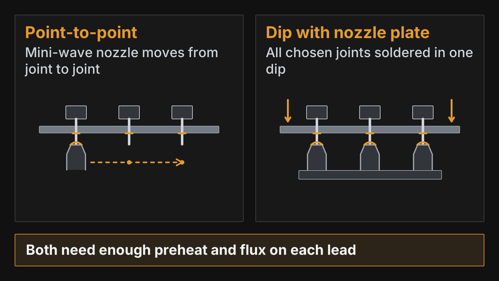
Figure 3. Point-to-point and dip selective soldering. Schematic based on the descriptions in Shoaf et al. and Diepstraten.
Two papers from 2023 describe why it is chosen:
- Shoaf, Clure and Jean of contract manufacturer Plexus describe selective soldering as typically used for hard-to-access and temperature-sensitive components. The flux system sprays directed amounts onto each lead, the solder pot and nozzle move on a gantry with adjustable dwell time, and because no wave pallet is needed the thermal mass is lower and preheat more balanced. Their paper focuses on high-layer-count, heavy-copper boards, where they found the window for full vertical hole fill narrows and process development matters as much as the machine.
- Diepstraten (Vitronics Soltec) notes that most assemblies still carry some through-hole parts, some because they cannot withstand reflow temperatures and others for mechanical strength, and that automotive assemblies add heavy three-dimensional connections. For those, he reports that robots using solder wire struggle with flux spattering and long cycle times, wave pallets limit wave height and pin-in-paste reflow is limited to two dimensions. A dip system with a dedicated nozzle plate solders all joints in one dip, but needs enough heat in the assembly first (often a forced-convection preheat) and must control hole fill, bridging and solder balls.
Selective soldering is also profiled differently. IPC-7530B treats it as a separate process with its own machine, preheat, solder pot and nozzle considerations, plus a section on copper dissolution.
Common mistake: Treating selective soldering as a slower wave. It is a different process, with its own preheat, flux placement and nozzle design, and it needs its own process development on the actual board.
Takeaway: Pick selective for a few demanding through-hole parts on an otherwise surface-mount board, and plan preheat and hole-fill checks from the start.
Where does hand soldering still make sense?
Hand soldering still makes sense for rework, prototypes, very low volumes and parts no machine can reach. Its weakness is the one Shoaf and colleagues highlight when they define selective soldering as machine repeatability with hand-soldering flexibility: a hand-soldered joint depends on the operator.
Here we compare hand soldering with flux-cored wire, whose core flux is classified the same way as the flux in solder paste. Shea, Arora and Brown point out that in hand or automated point-to-point soldering the flux in the wire is heated directly as it flows to the joint, which is different from wave flux spread across the board.
Automating hand soldering with a robot and solder wire is possible, but for the heavy three-dimensional assemblies discussed above, Diepstraten reports flux spatter and long cycle times as the obstacles. For small runs on ordinary boards, a hand-soldered through-hole part after reflow is often the simplest plan. If you are deciding between paste and wire for touch-up, our solder paste guide covers the materials.
Takeaway: Use hand soldering where flexibility matters more than repeatability, and write down the joints so they are inspected like any other.
Choosing a process for each part in four questions
Assign a candidate process to each part by working through the first three questions in order; if none applies, the fourth question chooses between selective and hand soldering. The result is a short table of candidate processes in your assembly notes for your assembler to confirm against their equipment and design rules.
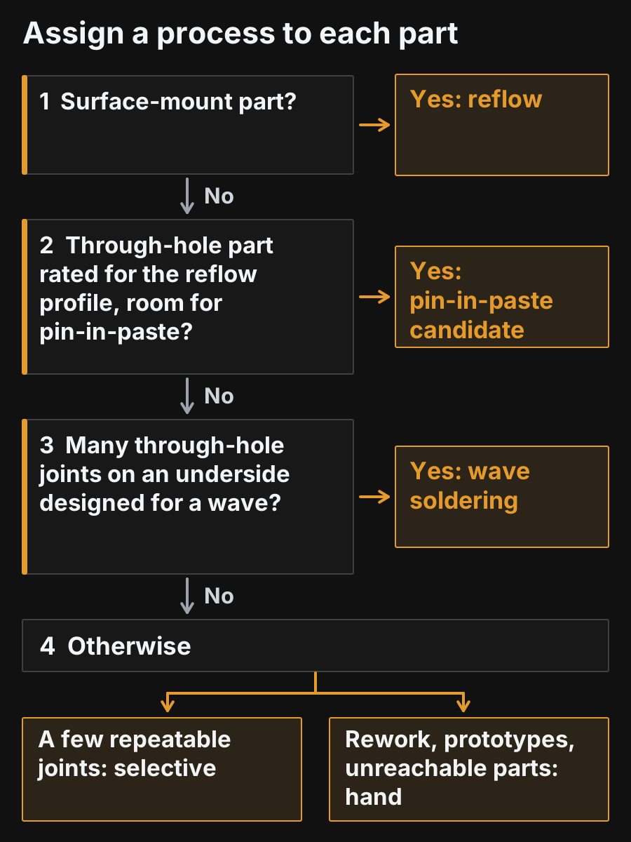
Figure 4. Four questions that assign a soldering process to each part. Our method, based on the sources above.
Question 1: Is the part surface-mount?
If yes, it goes through reflow with the rest of the surface-mount parts. Its limits are its maker’s assembly conditions, including the J-STD-020 classification for moisture-sensitive packages (our sources reproduce revision D.1), and the paste window; our five-step profile setup shows how both are checked.
Question 2: Can the through-hole part ride through reflow?
If its datasheet rates it for the reflow profile and its peak and the board has room for pin-in-paste (paste printed into and around the hole), list it as a pin-in-paste candidate; your assembler confirms the hole and pad design, paste volume and hole fill before it joins the reflow pass. If they cannot confirm it, go to Question 3. IPC-7530B covers paste-in-hole soldering as an alternative to selective soldering. Keep Diepstraten’s caution in mind: it is a flat, two-dimensional method with space limits.
Question 3: Are there many through-hole joints on an underside designed for a wave?
If yes, wave soldering can solder them in one pass. Check the underside layout and whether pallets are needed, and choose the flux with the whole-underside exposure in mind.
Question 4: Otherwise, selective or hand?
For a few joints that must be repeatable, choose selective soldering; for rework, prototypes and parts no machine can reach, choose hand soldering. Heavy-copper boards and 3D assemblies point to selective with a planned preheat.
Whatever the outcome, the joints are judged by the same acceptance criteria. IPC announced the J revisions of J-STD-001 (requirements for soldered assemblies) and IPC-A-610 (acceptability of assemblies) in April 2024, noting that the two documents are often used together; agree with your assembler which revision and class apply.
Takeaway: Record a candidate process per part in the assembly notes, then confirm it with your assembler’s equipment and acceptance class.
When this does not apply
This comparison covers tin-based soldering of mixed-technology printed circuit boards. Use other guidance in these cases:
- Press-fit and other solderless connections. These are mechanical processes outside this comparison.
- Laser soldering. IPC-7530B lists it as an alternative to selective soldering; it has its own process rules.
- Wire harnesses and cable assemblies. Separate workmanship standards and methods apply.
- Low-temperature or unusual alloys. The heat limits shift; start from the alloy comparison and the paste or bar-solder datasheet.
- A contract manufacturer’s fixed line. If your assembler only runs certain processes, the choice is theirs; give them the part list with heat ratings and let them assign.
Takeaway: If the joint is not a solder joint on a printed board, or the line is fixed, this per-part comparison is not the deciding tool.
Method and sources
Compiled on 7 October 2026 from public documents. This is a selection comparison based on public sources, not our own testing. The process descriptions come from three technical papers, each written by a company with a commercial interest in the topic (an equipment maker, a contract manufacturer and a flux maker), and from the table of contents of IPC-7530B; we use them for the mechanisms they describe, not for performance figures. The four-question method is ours. Sources are listed at the end of the page.
Related reading
Pick the next article by the part of the board you are working on.
- Reflow soldering explained: stages and temperature profile — Set the profile for the surface-mount side.
- Reflow oven types and how to choose one — Choose the oven for the reflow pass.
- How to choose solder paste — Pick the paste, including for pin-in-paste parts.
- All electronics manufacturing articles — Browse the rest of the SMT explainers.