The wrong solder paste costs you in rework: powder too coarse for the stencil leaves starved joints and opens, an alloy that melts too hot cooks the parts, and the wrong flux leaves residues your process cannot remove. Choose paste in three decisions, in this order: alloy (from your lead-free requirement and the heat your parts tolerate), powder type (from your smallest stencil aperture) and flux class (from whether you clean the board).
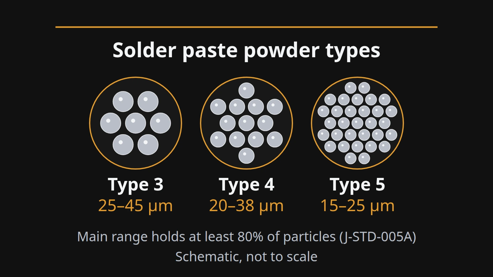
The short answer: Type 3 powder (at least 80% of particles 25–45 µm), Type 4 (20–38 µm) and Type 5 (15–25 µm) are size classes from IPC J-STD-005A, as reproduced in IPC and APEX conference papers (read October 2026). Under the “5-ball” rule from IPC-7525, the smallest printable aperture is about five times the largest particle in the main range: 9 mil for Type 3, 7.5 mil for Type 4 and 5 mil for Type 5. Apertures with an area ratio below 0.66 are where finer powders start to earn their extra cost. Alloy and flux are separate choices, and the paste datasheet ties all three to a reflow profile.
This guide walks through each decision with the tables you need to make it, then turns them into a five-step selection. It is compiled from public standards summaries, NIST data and published conference papers; it does not recommend brands or products.
| Input or item | Typical value or source | Why it matters |
|---|---|---|
| Smallest stencil aperture | Stencil drawing, mil or µm | Sets the finest powder type you need |
| Stencil foil thickness | Stencil drawing, mil | Needed for the area ratio |
| Area ratio of smallest aperture | Aperture area ÷ wall area; IPC guideline 0.66 | Below 0.66, paste release gets harder |
| Lead allowed or restricted | Product market and customer requirements | Chooses tin-lead or lead-free alloy |
| Part classification temperatures | J-STD-020D.1 Table 2B: 245–260 °C lead-free, by package thickness and volume | Limits how hot the alloy’s profile can run |
| Cleaning after reflow | Your process: none or washed | Chooses no-clean or water-soluble flux |
| Oven profile capability | Measured profile | The paste window must fit it |
What is in solder paste?
Solder paste is two materials mixed together: a solder alloy ground into fine, near-spherical powder, and a flux that carries the powder, holds parts in place and cleans the metal surfaces as it heats. EFD’s troubleshooting note puts it plainly: solder paste is actually two independent materials, flux and alloy. Each of the three decisions in this guide picks one property of that mixture.
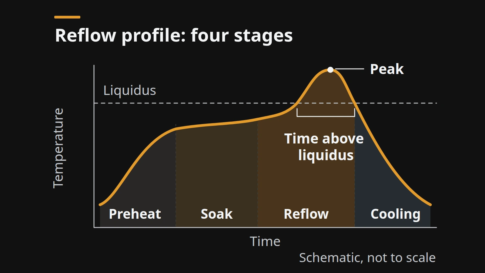
- The alloy decides the melting point and therefore the reflow profile and its four stages.
- The powder size decides which stencil apertures the paste can print through.
- The flux decides how the paste prints, how well it wets, and what residue stays on the board.
The powder and flux are formulated together. In Lentz’s APEX 2019 study, fluxes originally formulated for Type 3 and 4 powder were loaded with finer powders: the no-clean Type 6 paste and the water-soluble Type 5 and Type 6 pastes failed the hot slump test, while the others passed. The author’s conclusion is that a paste must be formulated for its powder size.
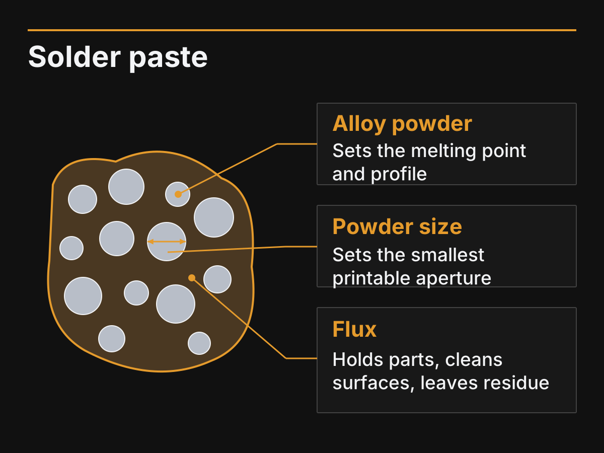
Figure 1. Solder paste is alloy powder suspended in flux; each selection decision changes one of the three. Schematic.
Takeaway: Treat alloy, powder and flux as three separate choices that the paste maker has already balanced in one product.
What do Type 3, Type 4 and Type 5 mean?
Type numbers are particle-size classes defined in IPC J-STD-005, the requirements standard for solder pastes. The headline range for each type is the band that holds at least 80% of the particles; the standard also caps how many particles may be larger or smaller. Larger type numbers mean finer powder.
The table reproduces the excerpt of J-STD-005A Table 3-2 published in Lentz’s APEX 2019 paper:
| IPC type | Less than 0.5% larger than | At most 10% between | At least 80% between | At most 10% smaller than |
|---|---|---|---|---|
| Type 3 | 60 µm | 45–60 µm | 25–45 µm | 25 µm |
| Type 4 | 50 µm | 38–50 µm | 20–38 µm | 20 µm |
| Type 5 | 40 µm | 25–40 µm | 15–25 µm | 15 µm |
| Type 6 | 25 µm | 15–25 µm | 5–15 µm | 5 µm |
Older tables, including one in O’Neill’s IPC-hosted paper, list Type 5 as 10–25 µm; the A revision uses 15–25 µm. The same paper lists the coarser Types 1 and 2 and the finer Types 7 (2–11 µm) and 8 (2–8 µm).
Lentz also gives a general rule of thumb for where each type is used: Type 3 for parts down to the 0402 imperial size, Type 4 for 0201 parts and micro-BGAs, and Type 5 for 01005 parts or when Type 4 does not print well. Types 5 and 6 are also used in dispensing and jet printing. Treat this as one author’s guidance, not a requirement; the stencil check in the next section is the actual test.
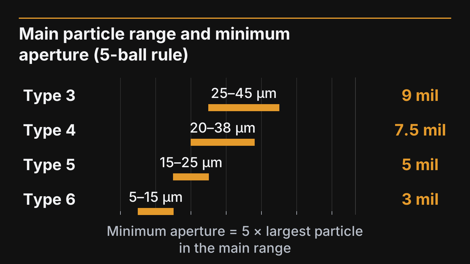
Figure 2. Main particle size range per type and the minimum aperture under the 5-ball rule (Lentz, APEX 2019).
Finer powder has costs. Because smaller particles have more surface area per gram, Lentz notes that they oxidize faster, need more flux activity during reflow, and can shorten stencil life and shelf life; Type 6 pastes in that study also failed the IPC solder balling test. O’Neill’s study adds that moving from Type 4 to Type 5 gave only a modest print benefit on small apertures, and that fine powder brings cost and supply-chain burdens.
Takeaway: Use the coarsest powder type that prints your smallest aperture reliably; finer is not better by default.
How do you match powder type to stencil apertures?
Match powder to stencil with two checks: the 5-ball rule for the smallest aperture width, and the area ratio for how readily paste leaves the aperture. The 5-ball rule screens the powder type; the area ratio depends only on the stencil geometry and flags a release risk that a powder change does not remove. When an aperture is below the guideline, a finer powder is one option to trial and a stencil change is the other.
Check 1: the 5-ball rule. IPC-7525, the stencil design guideline, uses the rule that at least five of the largest particles should fit across the smallest aperture. Lentz’s minimum apertures, calculated as five times the top of each type’s main range, are:
| Powder type | Main range | Minimum aperture (5-ball rule) |
|---|---|---|
| Type 3 | 25–45 µm | 9 mil (about 0.23 mm) |
| Type 4 | 20–38 µm | 7.5 mil (about 0.19 mm) |
| Type 5 | 15–25 µm | 5 mil (about 0.13 mm) |
| Type 6 | 5–15 µm | 3 mil (about 0.08 mm) |
Check 2: the area ratio. The area ratio is the aperture opening area divided by the area of its walls; for a round or square aperture it reduces to the width divided by four times the foil thickness (AR = D/4T, as given in O’Neill’s paper). IPC’s guideline value is 0.66. Below it, paste tends to stay in the aperture instead of transferring to the pad.
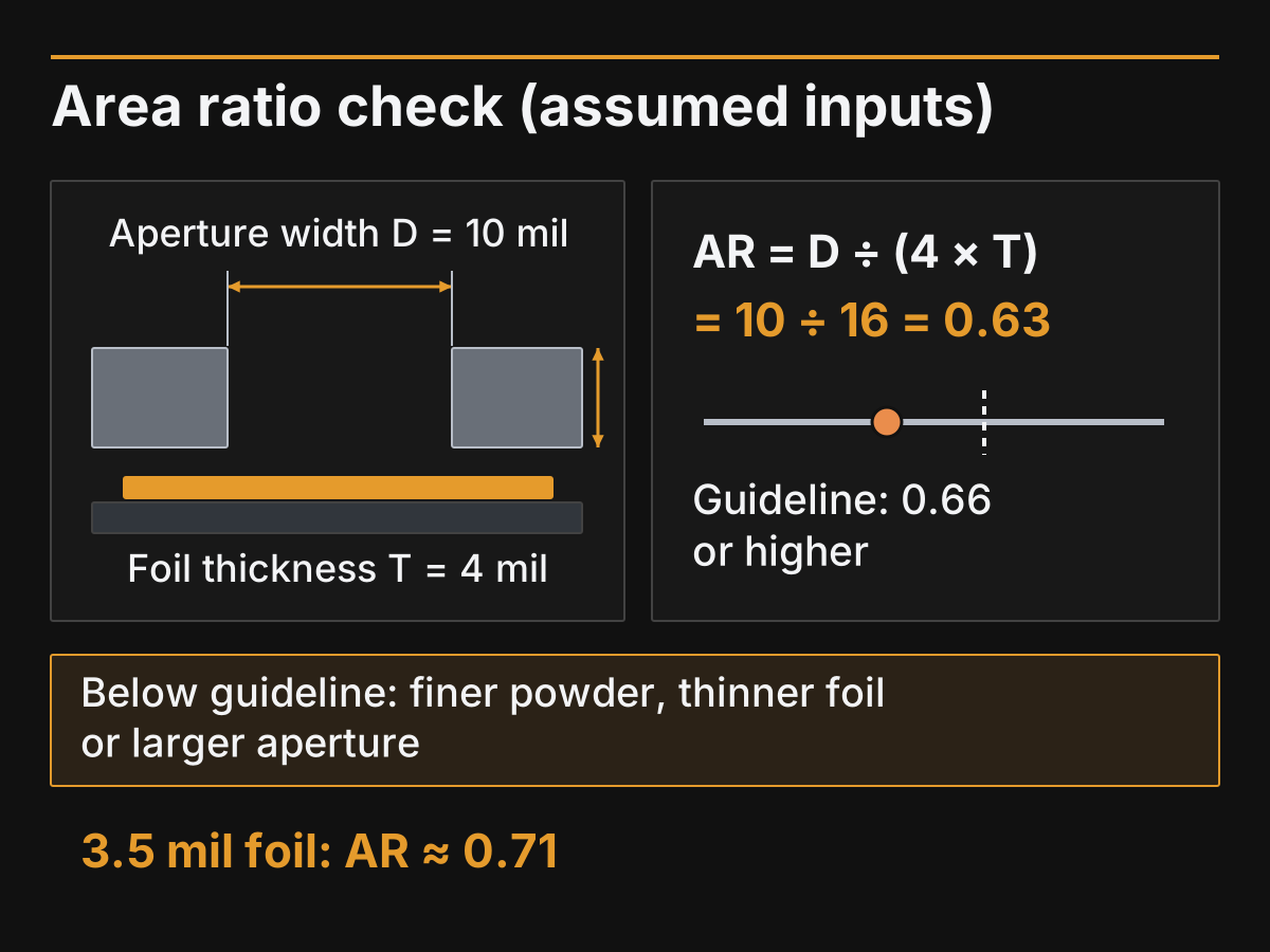
Figure 3. Worked example with assumed inputs: a 10 mil aperture in a 4 mil foil gives AR = 0.63, below the 0.66 guideline.
Worked example (assumed inputs, not a test): a 10 mil round aperture in a 4 mil foil gives 10 ÷ (4 × 4) = 0.63, which matches O’Neill’s table for a 4 mil foil and sits below 0.66. Type 3 passes the 5-ball rule at 10 mil, but the area ratio flags a release risk to confirm with a trial print. The options to trial are a finer powder (Type 4 or 5), a thinner foil (a 3.5 mil foil would give about 0.71) or a larger aperture if the pad allows it.
Common mistake: Switching to Type 5 to fix a stencil problem. O’Neill’s study concluded that paste formulation, stencil coatings and under-stencil wiping can affect transfer efficiency as much as powder size, and that the Type 4 to Type 5 gain on small apertures was modest. Check the area ratio and the stencil first.
To see how print quality shows up after reflow, read the defect table in our reflow profile explainer.
Takeaway: Compute the area ratio for your smallest aperture before choosing a powder; it often points to a stencil change instead.
Which alloy: tin-lead, lead-free SAC or low-temperature tin-bismuth?
Choose the alloy first, because it sets the reflow temperatures every part on the board must survive. Use lead-free tin-silver-copper (SAC) where lead is restricted, tin-lead where it is still permitted, and tin-bismuth when parts or boards cannot tolerate lead-free reflow heat.
| Alloy family | Example | Melting behavior | Where it fits | Watch for |
|---|---|---|---|---|
| Tin-lead | Sn63Pb37 | Eutectic, 183 °C (NIST calculated 182.2 °C) | Products where lead is permitted | Lead restrictions in your market |
| Lead-free SAC | Sn96.5Ag3.0Cu0.5 (SAC305) | Solidus 217 °C, liquidus 219 °C (EFD alloy table); NIST SAC ternary eutectic 215.9 °C | General lead-free assembly | Higher peak; parts must carry lead-free J-STD-020 ratings |
| Low-temperature tin-bismuth | Sn42Bi58 | Eutectic, 138 °C (NIST calculated 138.8 °C) | Heat-sensitive parts and boards, rework | Needs its own profile and joint reliability checks |
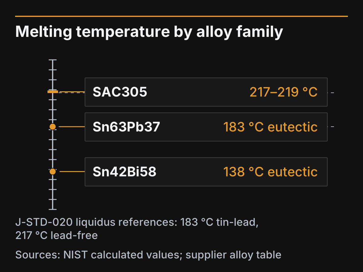
Figure 4. Melting points of the three alloy families (NIST calculated values and a supplier alloy table).
Regulation usually decides between the first two. The European Union’s RoHS Directive restricts ten substances in electrical and electronic equipment, including lead, with exemptions listed in its annexes (European Commission, read October 2026). Check the requirements of every market you ship to and your customer’s specification.
Heat decides the third. Sandy, Briggs and Lasky’s SMTA paper on bismuth-based alloys notes that the higher reflow temperatures of lead-free assembly can thermally damage boards and components, which is the main reason low-temperature alloys exist. The trade-off is that a tin-bismuth paste needs its own profile and its own reliability evaluation for your product.
The alloy also fixes the classification column for your parts: components used in lead-free assembly are rated with J-STD-020’s lead-free table. Our explainer on J-STD-020 limits shows how those ratings cap the profile, and the oven guide’s specification checklist covers whether your oven can hold it.
Takeaway: Let regulation and part ratings choose the alloy; the rest of the paste choice follows from it.
Which flux class fits your cleaning process?
Pick the flux by what happens after reflow. If the board is not washed, use a no-clean paste whose residue is designed to stay on the board; if you wash, a water-soluble paste is an option and the washing step becomes part of the process. The J-STD-004 code on the datasheet tells you the flux’s composition and activity.
J-STD-004 classifies every soldering flux, including the flux in solder paste and in cored wire, with a short code. As summarised for revision A in an IPC-hosted paper by Shea, Arora and Brown:
| Code part | Options | Meaning |
|---|---|---|
| Composition | RO, RE, OR, IN | Rosin, resin, organic, inorganic (inorganic fluxes are not used in electronics assembly) |
| Activity | L, M, H | Low, moderate or high flux and residue activity |
| Halide | 0 or 1 | Halides absent (0) or present (1) |
So ROL0 means a rosin flux with low activity and no halide. Later revisions changed the halide thresholds behind the 0 and 1, so read the revision stated on the datasheet.
The same paper notes that when an acceptable joint forms in reflow, a no-clean paste’s residue has seen enough heat to become non-corrosive in the areas where it was printed. A water-soluble paste is instead designed around a washing step. Either way, check the paste datasheet’s reflow window and your product’s residue or cleanliness requirements before choosing.
Common mistake: Adding extra liquid flux during rework without checking it against the paste and the rework procedure. The added flux has not seen the same heat as the printed paste and is outside the paste’s qualification.
Takeaway: Decide whether you wash the board, then choose the flux class and read its J-STD-004 code on the datasheet.
Choosing a solder paste in five steps
The three decisions above become a five-step selection when you add the profile check and the handling plan. The output is a one-line paste specification (alloy, type, flux class) plus a profile and storage plan you can verify.
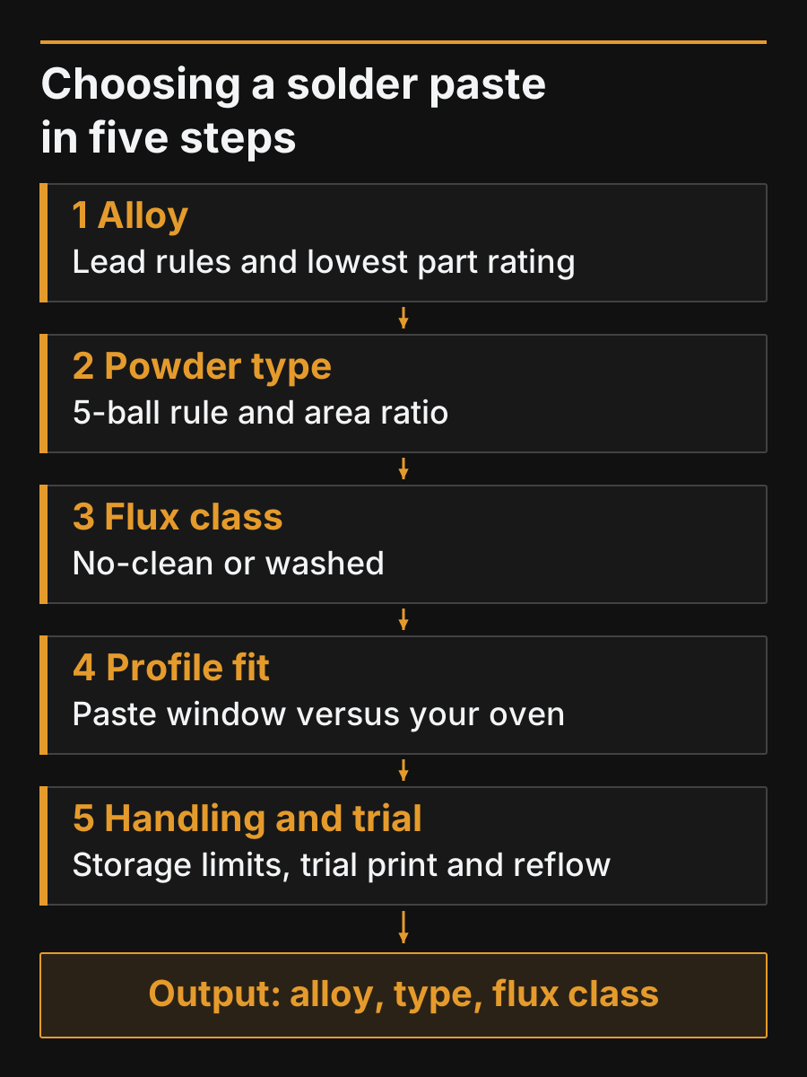
Figure 5. Choosing a solder paste in five steps. Each step fixes one line of the specification.
- Fix the alloy. From lead restrictions in your markets and the lowest classification temperature on your parts list.
- Fix the powder type. Apply the 5-ball rule to the smallest aperture and choose the coarsest type that passes it; if the area ratio is below 0.66, plan a trial print or a stencil change as well.
- Fix the flux class. No-clean if the board is not washed; water-soluble only if washing is in the process.
- Check the profile fit. Compare the paste datasheet’s soak, time above liquidus and peak against what your oven can hold on your heaviest board; our five-step profile setup covers the measurement.
- Plan handling and verify. Follow the datasheet’s storage and stencil-life limits (Lentz notes that finer powders can shorten both), then print and reflow a trial board and inspect it before committing.
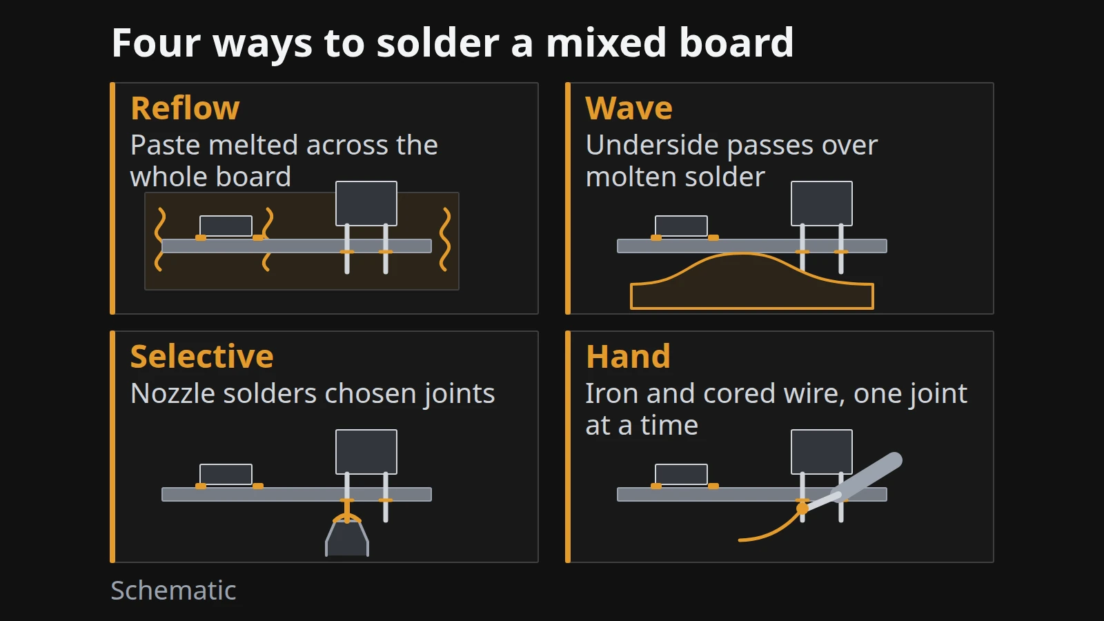
If you are still deciding how through-hole parts on the same board will be soldered, that choice affects whether paste is the only solder on the board; see our comparison of wave, reflow, selective and hand soldering.
Takeaway: A paste choice is finished only after a trial print and reflow on your own stencil and oven.
When this does not apply
This guide covers solder paste printed through a stencil for surface-mount reflow of electronics. Use other guidance in these cases:
- Hand soldering and touch-up. Flux-cored wire is the usual material, and the same J-STD-004 flux codes apply to its core; our comparison covers where hand soldering still makes sense.
- Jetting and dispensing. Types 5 and 6 are used for jet printing and dispensing, and the paste is formulated for that process; the 5-ball rule for stencils does not apply.
- Through-hole parts. Wave or selective soldering uses bar solder and liquid flux; see our process comparison.
- Non-electronics pastes. Plumbing, jewelry and stainless-steel pastes use different alloys and fluxes and are outside this guide.
- Customer material and cleanliness specifications. If your customer specifies the alloy, flux class or cleanliness testing, those requirements come first.
Takeaway: If the paste is not printed for reflow, start from the process you are using rather than from this selection.
Method and sources
Compiled on 7 October 2026 from public documents; we did not test any paste. J-STD-005A powder classes and the 5-ball rule are taken from conference papers that reproduce them (Lentz, APEX 2019; O’Neill et al., hosted by IPC); we did not read J-STD-005A or IPC-7525 themselves. Both papers are written by paste makers; we use them for the standard tables and their stated findings, not for product claims. Melting points come from NIST calculated phase diagrams and a supplier alloy table. J-STD-004 codes are taken from an IPC-hosted paper describing revision A. Sources are listed at the end of the page.
Related reading
Pick the next article by the decision you are on.
- Reflow soldering explained: stages and temperature profile — See how the paste window becomes an oven profile.
- Reflow oven types and how to choose one — Check whether your oven can hold the paste’s profile.
- Wave vs reflow vs selective vs hand soldering — Decide how the through-hole parts get soldered.
- All electronics manufacturing articles — Browse the rest of the SMT explainers.