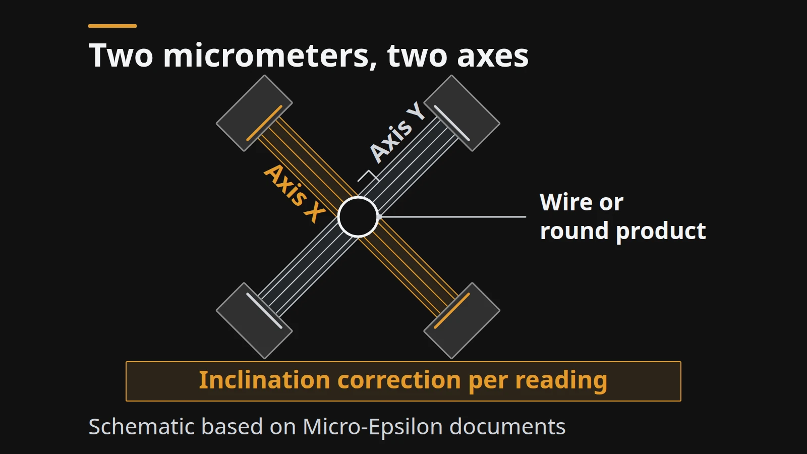
Planning a PLC integration around the headline specs of a new inline micrometer can cost commissioning days when the fieldbus variant, the IP addresses or the measuring rate turn out different. Micro-Epsilon’s profileGAUGE C.ODC is two optoCONTROL 2700 micrometers pre-mounted in an X, and the published setup guide treats it as two devices on the network: each needs its own address and, for PROFINET, EtherCAT or EtherNet/IP, its own interface or on-board fieldbus option.
What is confirmed: Instrumentation Monthly reported the system on 6 October 2026 from Micro-Epsilon’s announcement, and Micro-Epsilon’s own product page, datasheet and setup guide are online with device description files for EtherCAT (ESI), PROFINET (GSDML) and EtherNet/IP (EDS). All figures below are manufacturer data; none has been independently tested. What is not published: US price, stock and lead time, and a single answer on the measuring rate, which the press report gives as 5,000 per second and the US datasheet as 15 kHz.
What did Micro-Epsilon announce?
Micro-Epsilon announced profileGAUGE C.ODC as an inline system that measures the diameter, contour and position of fine wires and small round products on two axes at once, using two of its optoCONTROL 2700 micrometers in an X arrangement. The product pages were online before the October press coverage, so treat October 2026 as the date of the news report, not the launch, the same check we applied to HARTING’s two Size 4 announcements.
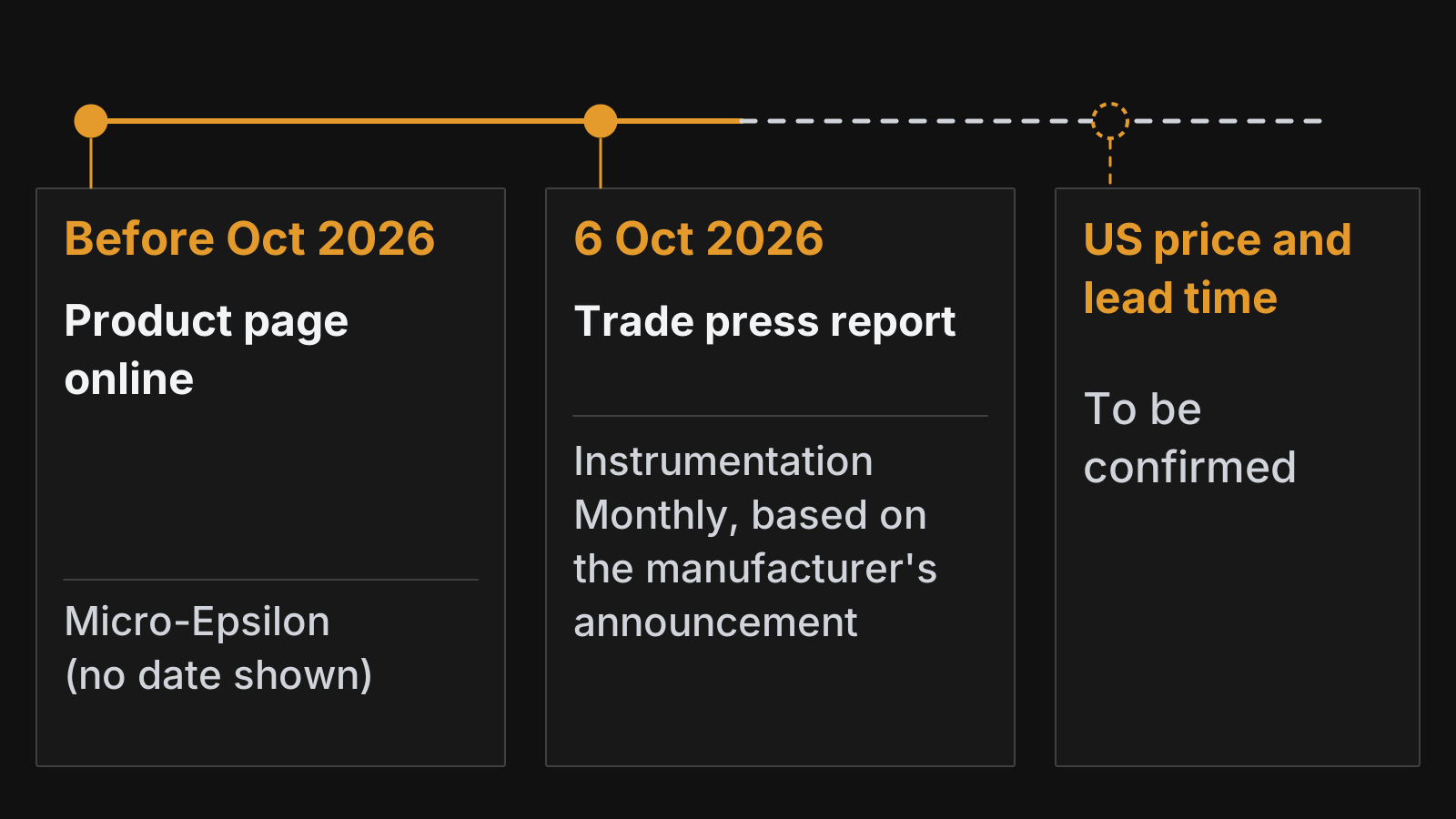
Figure 1. What was published when. All content originates from Micro-Epsilon.
| Date | Event | Source | Source type |
|---|---|---|---|
| Before October 2026 (date not shown) | Product page online (captured in our research records before October) | Micro-Epsilon | Manufacturer |
| 6 October 2026 | Report: two ODC2700 in X arrangement, from 30 µm, fieldbus interfaces, inclination correction | Instrumentation Monthly | Trade media, based on the manufacturer’s announcement |
| Checked 7 October 2026 | Datasheet, setup guide and device description files downloadable; US page lists US regional offices; no US price or lead time shown | Micro-Epsilon US site | Manufacturer |
Both describe active inclination correction for tilted targets and contamination detection that reports the optics as clean, restricted or soiled.
Takeaway: This is a manufacturer announcement with full documents online; plan from the documents, not the press summary.
Which published specs matter for integration?
For integration, the specs that matter are the measuring range and minimum target, the measuring rate, the interfaces and inputs, and the environmental limits, and several of them carry conditions that the headline figures leave out. The table lists each with its condition and source.
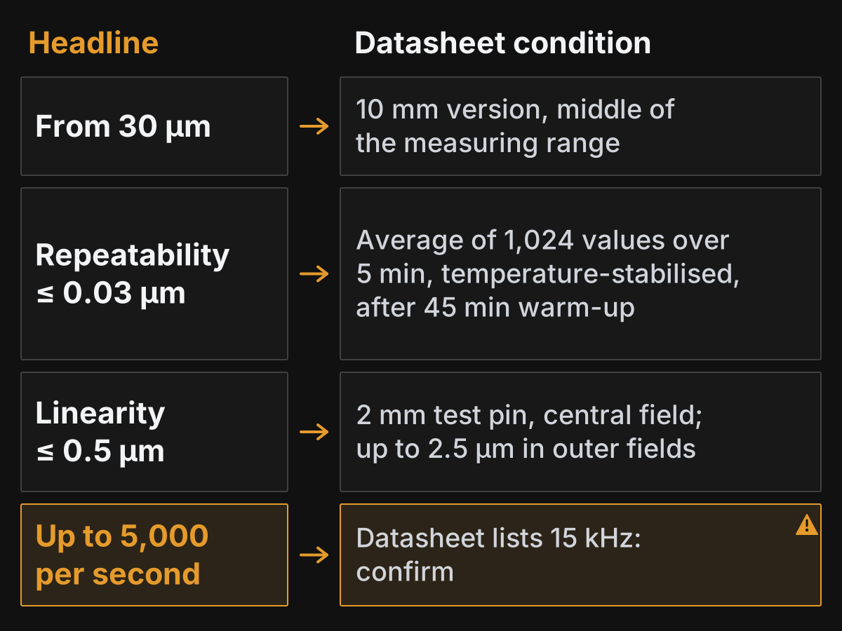
Figure 2. Headline figures and the conditions attached to them in the datasheet.
| Spec | Published value | Condition | Source |
|---|---|---|---|
| Measuring range | 10 mm or 40 mm | Two model families (C.ODC-10/2 and C.ODC-40/2, each with protective glass and air-purge variants) | Datasheet |
| Minimum target | 0.05 mm (0.03 mm mid-range) for 10 mm; 0.3 mm (0.1 mm mid-range) for 40 mm | Mid-range values apply in the centre of the measuring field | Datasheet |
| Linearity, 10 mm | ≤ 0.5 µm (Z ±0.5 mm), ≤ 1 µm (Z ±1.5 mm), ≤ 2.5 µm (Z ±2.5 mm) | 2 mm test pin at 150 mm; footnote conditions below | Datasheet |
| Linearity, 40 mm | ≤ 1 µm (Z ±2.5 mm), ≤ 3 µm (Z ±10 mm) | 2 mm test pin at 150 mm; footnote conditions below | Datasheet |
| Repeatability | ≤ 0.03 µm (10 mm), ≤ 0.1 µm (40 mm) | Footnote conditions below | Datasheet |
| Resolution | 10 nm | At the digital interface | Datasheet |
| Measuring rate | 5 kHz (press, product page); 15 kHz (datasheet) | Sources differ; confirm for your interface | Press report; product page; datasheet |
| Exposure time | 8.5 µs | With video averaging on, each measurement uses 3 × 8.5 µs exposures | Datasheet; press report |
| Supply | 11–30 VDC, ≤ 1 A | Setup guide gives 24 VDC as typical | Datasheet; setup guide |
| Protection, temperature | IP67 with protective glass and cables connected; 0–50 °C operating | — | Datasheet |
| Weight and mounting | 26 kg; 8 × M10 or 8 × M12 screws | Frame for both micrometers | Datasheet |
The datasheet’s footnote for both linearity and repeatability: 95% confidence interval, diameter measurements averaged over 1,024 values across 5 minutes, temperature-stabilised, after 45 minutes warm-up. Z is the distance from the centre of the measuring field. Repeatability is the figure most likely to be misread: it describes agreement between averaged readings under controlled conditions, not single-reading accuracy on a moving line. The same habit of reading figures with their conditions applies to other recent announcements, such as HARTING’s connector space and weight figures.
Common mistake: Quoting 0.03 µm repeatability as the accuracy of the gauge. The datasheet lists linearity separately, and both come from averaged, temperature-stabilised tests.
Takeaway: Copy each spec into your design notes with its datasheet condition, and resolve the 5 kHz versus 15 kHz difference before sizing the PLC cycle.
How does it connect to a PLC over EtherCAT or PROFINET?
Plan the system as two micrometers that share a frame, a sync line and an encoder input: each one connects to the network on its own, either with an on-board fieldbus (available on request) or through a Micro-Epsilon interface module, and the PLC combines the two axes. The steps below follow the setup guide and the product page downloads.
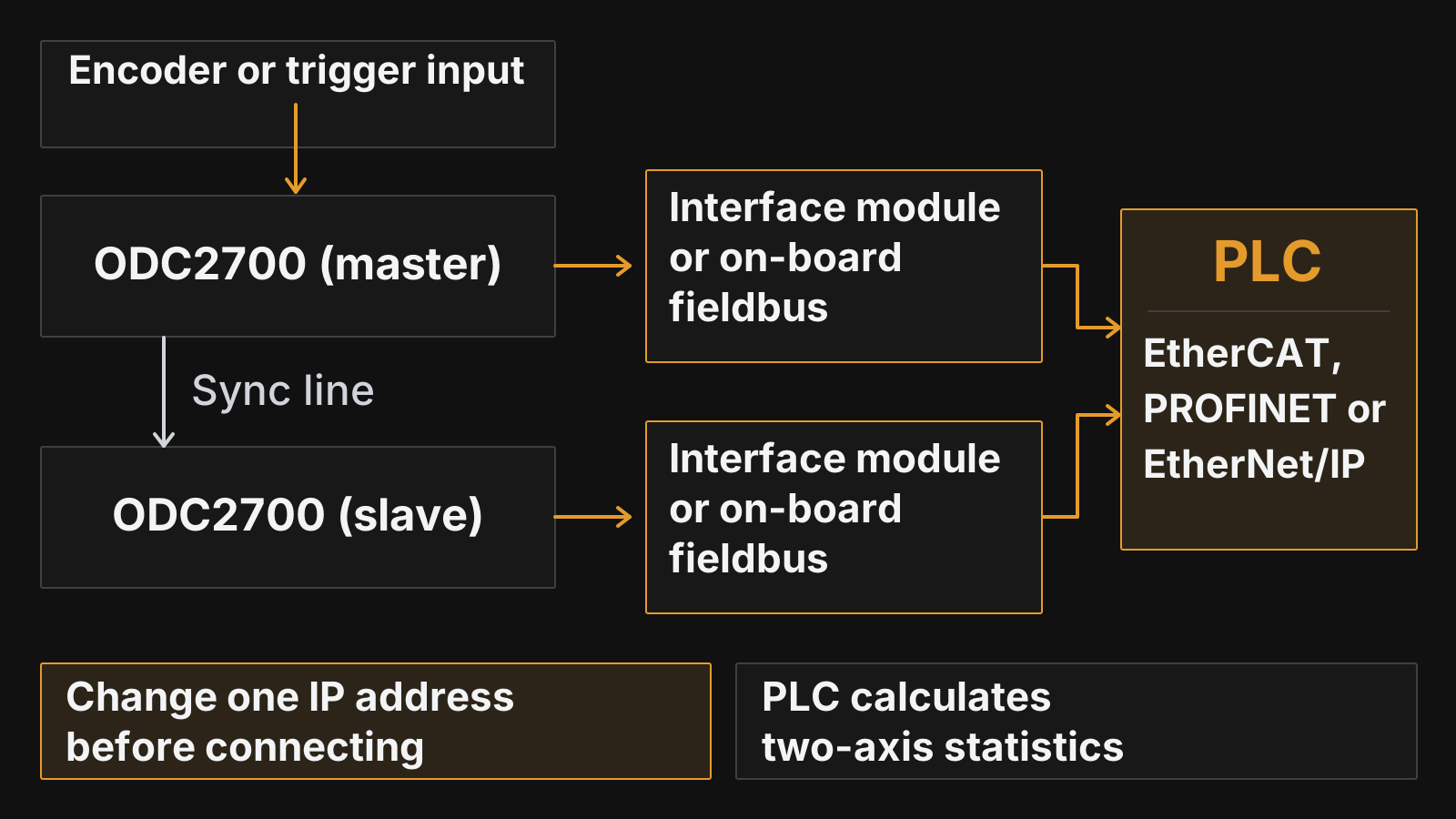
Figure 3. Integration topology as described in the setup guide. Module names are Micro-Epsilon’s.
- Choose the fieldbus route. The datasheet lists Ethernet and RS422 as standard and EtherCAT, EtherNet/IP or PROFINET either on board on request or through an interface module. The setup guide’s fieldbus example uses IF2035-PROFINET, IF2030-EtherCAT or IF2035-EIP modules, and its interface table lists two IF2035 modules to run one system.
- Load the device descriptions for your route. For on-board fieldbus, the product page offers an ESI file for EtherCAT, a GSDML file for PROFINET and an EDS file for EtherNet/IP, each labelled for the ODC2700, with firmware for the PROFINET and EtherCAT versions (both V12.0) and Ethernet (V14.2). If you use IF2035 or IF2030 interface modules, confirm the module’s own files and firmware with Micro-Epsilon; the page we checked does not list them.
- Separate the sensor addresses. Both micrometers ship with the same static IP address on their sensor LAN port; change one before connecting both, as the setup guide instructs. Fieldbus node addressing is a separate step in your PLC tool.
- Wire synchronisation. Micro-Epsilon recommends synchronising the two micrometers: the sync output of the first (master) goes to the sync input of the second (slave), so both axes measure the same section of the product.
- Wire an encoder or trigger if you need one. Multifunction inputs can be programmed as trigger or encoder inputs (tracks A, B and reference); the setup guide lists both 24 V HTL and 5 V TTL logic levels, so match the input to your signal. With an encoder configured, each measured value can be tied to a line position.
- Set the measuring mode and save it. Micro-Epsilon recommends the Diameter preset on both micrometers; then select the output values and save the settings as a setup so they load at start-up. Check how outputs map to your fieldbus route with Micro-Epsilon.
- Do the maths in the PLC. Micro-Epsilon states that statistics from both axes are calculated on the customer side, in the control system or a higher-level system.
Our FLIR Prism A-ISR checklist applies the same document-first planning to edge-AI software running on embedded hardware.
Takeaway: Budget two fieldbus nodes and a sync cable per system, add an encoder or trigger input if your line needs one, and settle the fieldbus route before ordering.
Integration readiness checklist
Use this checklist before PLC engineering starts. Each line points to the document that answers it or marks it for confirmation, as in our HARTING open-items table.
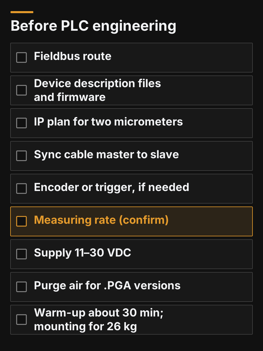
Figure 4. Readiness checklist with the source document for each item.
| Item | Where to find it | Why it matters |
|---|---|---|
| Fieldbus route: on board or interface modules | Datasheet footnote; setup guide | Sets part numbers and cabinet space |
| Device description files and firmware versions | Product page downloads | Must match the PLC engineering tool |
| IP address plan for two micrometers | Setup guide | Both ship with the same address |
| Sync cable between master and slave | Setup guide | Keeps both axes on the same product section |
| Encoder or trigger, if needed: 24 V HTL or 5 V TTL | Setup guide | Ties readings to line position or an external trigger |
| Diameter preset on both units, outputs selected, setup saved | Setup guide | Same measuring mode on both axes after restart |
| Measuring rate for your interface | Confirm with Micro-Epsilon | Sources give 5 kHz and 15 kHz |
| Supply 11–30 VDC and current per unit | Datasheet; setup guide | Sizes the power supply |
| Purge air to DIN ISO 8573-1:2010 [1:4:2] | Setup guide (air-purge versions) | Needed only for the .PGA versions |
| Warm-up (about 30 minutes) and mounting for 26 kg | Setup guide; datasheet | Affects start-up routine and frame design |
Takeaway: When every row has an answer, PLC engineering can start.
Who is affected?
The system targets inline quality control of fine wire, glass fibre, precision tubes, medical device parts, transparent parts and bar stock, especially where tilt or vibration disturbs single-axis measurement.
| Reader | What changes | Basis |
|---|---|---|
| Automation integrators | Two fieldbus nodes, sync and encoder wiring per gauge | Setup guide |
| Quality engineers | Two-axis diameter and position with inclination correction; conditions on repeatability and linearity | Datasheet |
| US buyers | US website and regional offices listed; no US price or lead time shown | US product page |
The edge-processing side of similar systems is covered in our embedded systems articles.
Takeaway: Integrators carry most of the new work; quality teams mainly need the datasheet conditions.
When should integrators act?
Start technical evaluation now, since all the documents are downloadable; ordering and commissioning wait on a US quotation and the measuring-rate answer.
| When | Action | Status |
|---|---|---|
| Now | Download datasheet, setup guide, STEP model and ESI, GSDML or EDS files | Available on the product page |
| Now | Ask Micro-Epsilon’s US office for price, lead time and the fieldbus option | To be confirmed |
| Before PLC engineering | Confirm the measuring rate for your interface | To be confirmed |
| Before installation | Plan mounting for 26 kg, purge air if used, warm-up time | From the documents |
Takeaway: Start with the documents now and hold commissioning plans until the quotation arrives.
What is still unconfirmed?
The measuring rate, US price and lead time, and performance on your own product are the open items that decide a project. Each one below lists who can confirm it.
- Measuring rate: 5 kHz in the report and product page, 15 kHz in the datasheet. Micro-Epsilon.
- US price, stock and lead time: not shown in the sources we checked. Micro-Epsilon’s US office.
- Performance on your product: the sources we checked contain no independent test, and the datasheet conditions are laboratory conditions. A trial on your material.
- Limits on transparent materials, and any effect of the protective glass: not quantified in the sources we checked. Micro-Epsilon or a trial.
- First release date: the product pages predate the October report, with no date shown. Micro-Epsilon.
Open items in other vendor announcements, such as the unpublished detection data for FLIR Prism A-ISR, are listed the same way.
Takeaway: Put the open items into the quotation request.
Our reading
For integrators, the useful news is that the documents for a fieldbus integration are already public, and they show a two-node design rather than a single box. The open measuring-rate question is the one item that could change a PLC design. More industrial announcements are covered in our industrial electronics section, and this independent site has no connection with Micro-Epsilon; all our explainers are listed on the blog index.
Takeaway: Plan from the datasheet and setup guide, and get the measuring rate in writing.
When this does not apply
This page prepares the integration of the dual-axis system; it does not cover other set-ups or approve performance.
- Single-axis ODC2700 installations. The two-node and sync points are specific to the dual-axis system.
- Acceptance of measurement capability. That needs a gauge study on your line, not datasheet figures.
Takeaway: Use this page to prepare an integration, not to approve gauge performance.
Method and sources
Compiled on 7 October 2026 from Micro-Epsilon’s US product page, datasheet and setup guide (no publication dates shown), and the Instrumentation Monthly report of 6 October 2026, which counts as the same source. We did not test the system. We will update this page if Micro-Epsilon clarifies the measuring rate or US availability.
Takeaway: Recheck the datasheet and firmware versions on the product page before ordering, since neither shows a date.