A reflow profile that runs too cool leaves unmelted or weak joints, and one that runs too hot can damage the parts it was meant to attach. Reflow soldering melts printed solder paste in a controlled heat cycle of preheat, soak, reflow and cooling; the solder paste datasheet sets the process window, and each component’s J-STD-020 classification temperature sets the ceiling.
Keep two sets of numbers apart. The component limits come from IPC/JEDEC J-STD-020: for lead-free assembly, a package body peak of no more than 245–260 °C depending on package thickness and volume (as reproduced by component makers, read October 2026). The process window (how long the joints stay above the solder’s liquidus, the temperature at which it is fully molten, and how high the peak goes) comes from the solder paste datasheet. A profile is right when measurements on the real board satisfy both.
This page explains each stage, which numbers are hard limits, how to set a profile for a specific board, and which defects point back to the profile. It is compiled from public standards summaries, NIST data and published technical papers, not from our own trials.
| Input or item | Typical value or source | Why it matters |
|---|---|---|
| Liquidus reference | 217 °C lead-free, 183 °C tin-lead (J-STD-020 tables) | Reference line for time above liquidus (TAL) |
| Production TAL and peak target | Solder paste datasheet | The paste maker defines when joints form properly |
| Package peak ceiling | 245–260 °C lead-free, by thickness and volume (J-STD-020D.1 Table 2B) | Each part is qualified only up to its own value |
| Classification TAL | 60–150 s (J-STD-020) | Describes the qualification test, not a production minimum |
| Moisture sensitivity level (MSL) | Label on the part’s dry pack | Says whether parts need baking before reflow |
What is reflow soldering and how does it work?
Reflow soldering joins surface-mount parts by melting solder that is already on the board. A stencil prints solder paste (fine solder powder suspended in flux) onto each pad, a placement machine sets the parts into the wet paste, and the assembly then passes through a heat cycle that melts the powder into a single joint per lead.
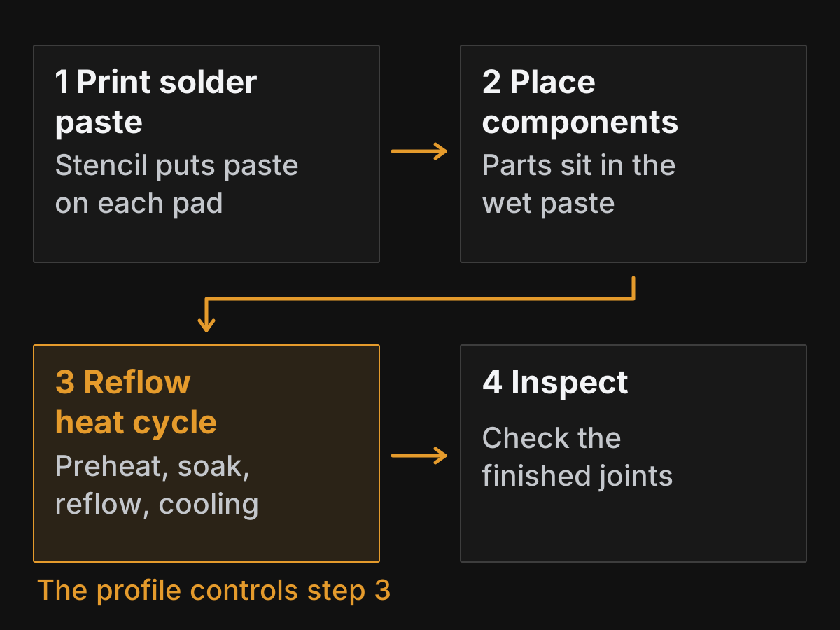
Figure 1. The reflow assembly sequence. The profile only controls the third box, but print and placement errors show up as reflow defects.
The flux matters as much as the metal. It holds the parts in place before melting, cleans oxide from the pads and leads as it heats, and lets the molten solder wet both surfaces. ACI Technologies, an IPC training and test centre, notes in its 2019 profiling tip that lead-free pastes have higher surface tension than tin-lead and do less to pull slightly misplaced parts back into position, which makes print and placement accuracy more important.
The heat has to reach every joint on the board, including joints under large packages and next to copper planes, without overheating the smallest parts. That balance is what a temperature profile describes: a temperature-versus-time record taken from thermocouples on representative components as the board moves through the oven, in the definition used by IPC’s profiling guideline.
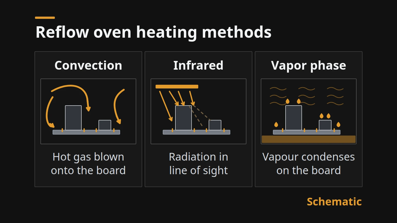
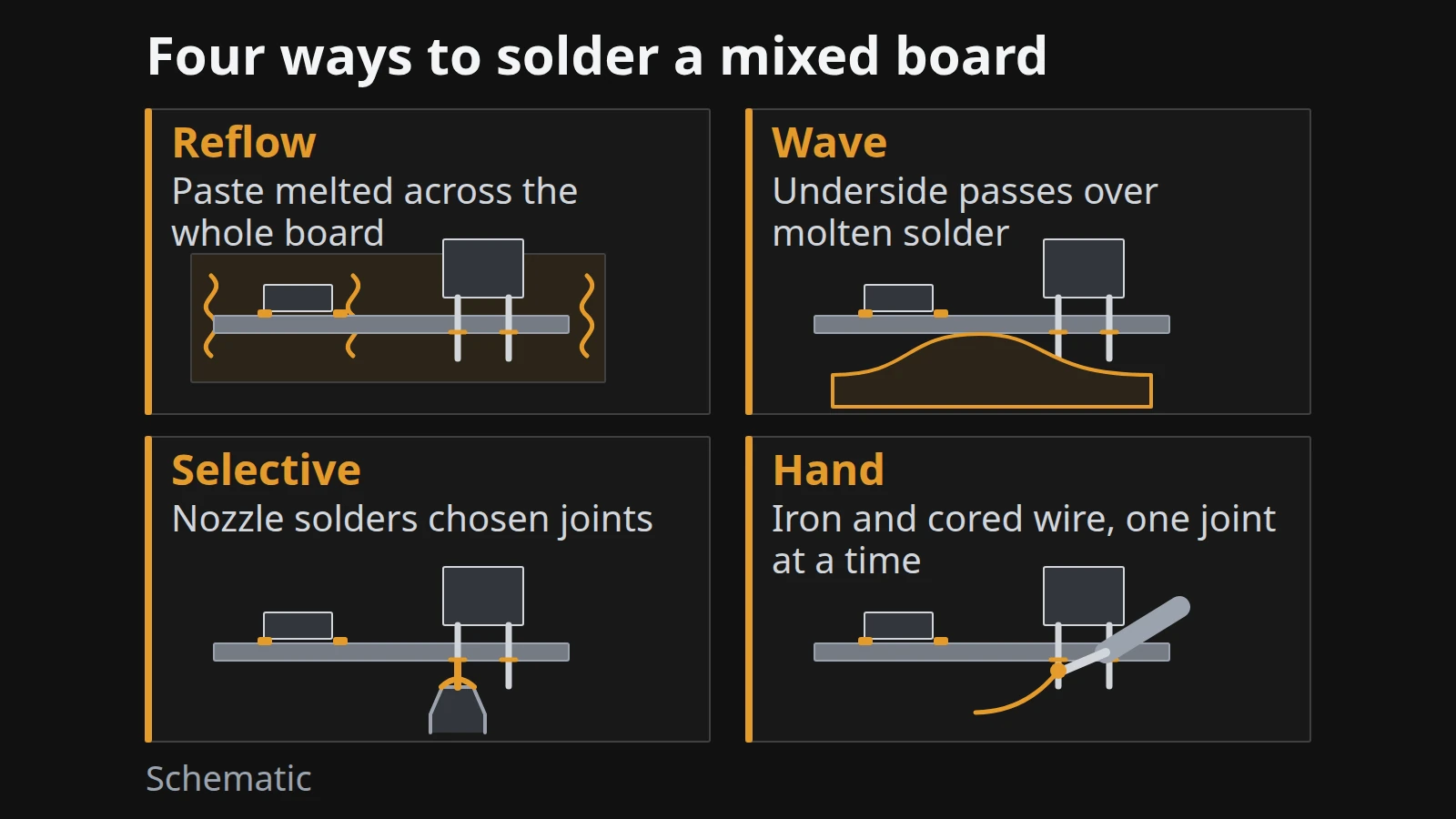
Through-hole parts that cannot take this heat cycle need a different process; our comparison of wave, selective and hand soldering shows how to assign one per part. If you are still deciding which oven design to use, our comparison of convection, infrared and vapor-phase reflow ovens covers that choice; this page assumes the oven exists and focuses on the profile.
Takeaway: Reflow is a print–place–heat process; the profile is the part you tune, but it only works on a good print.
What are the four stages of a reflow profile?
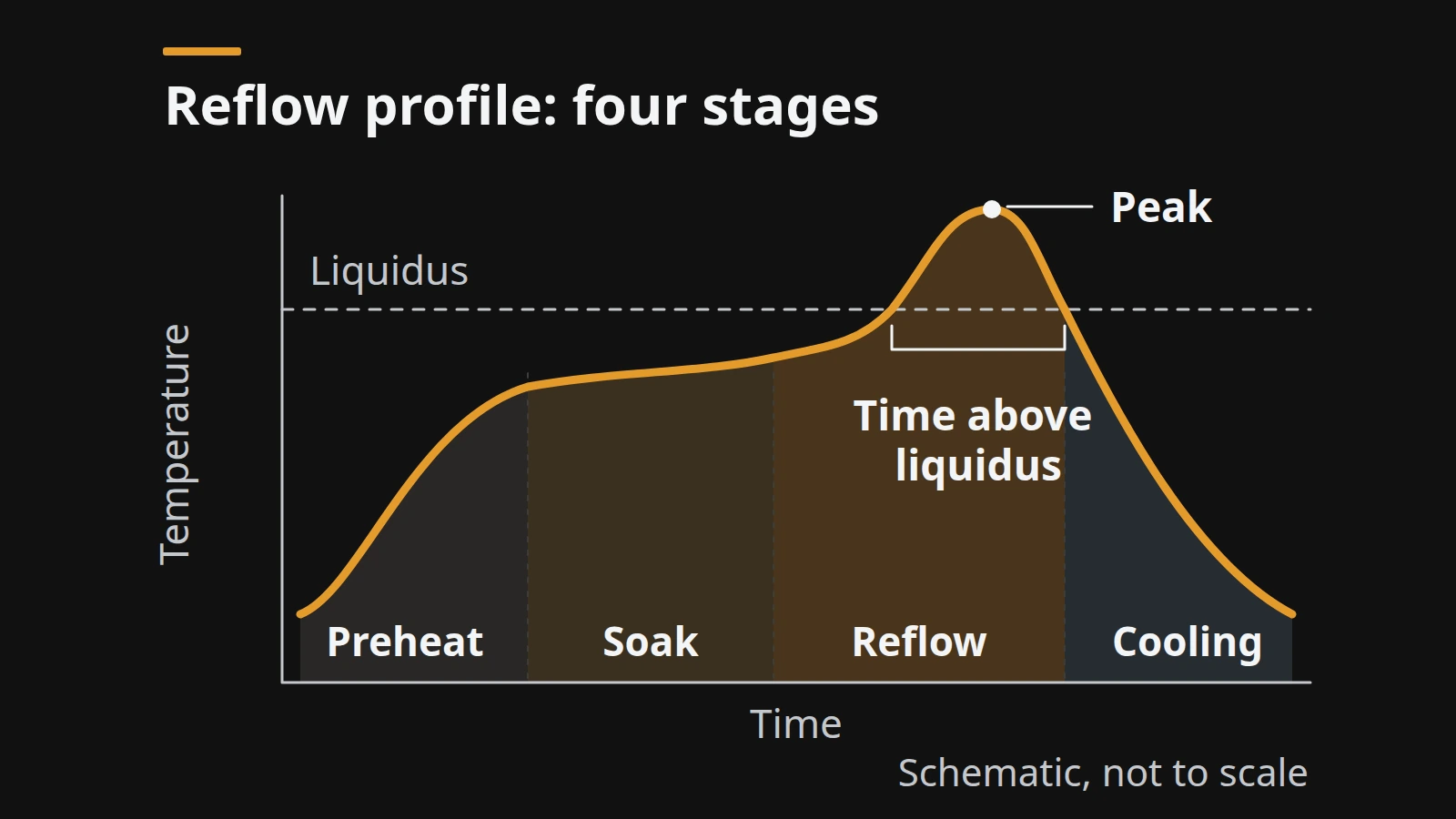
A reflow profile has four stages, and each one does a different job: preheat drives off solvents, soak evens out the board temperature and activates the flux, reflow takes the joints above the solder’s liquidus, and cooling solidifies them. The schematic at the top of this page shows the four stages on one curve; the table maps each stage to what it controls and where the numbers come from.
| Stage | What happens | What you control | Where the limit comes from |
|---|---|---|---|
| Preheat | Low-boiling solvents and moisture evaporate; the board warms from room temperature | Ramp rate | Paste datasheet |
| Soak | Board and large parts catch up with small parts; flux activates | Soak temperature and time | J-STD-020 classification soak: 150–200 °C for 60–120 s (lead-free) |
| Reflow | Solder passes liquidus, wets pads and leads, reaches peak | Time above liquidus (TAL), peak temperature, ramp to peak | Paste datasheet for the TAL and peak window; each part’s Tc caps its package temperature; J-STD-020 caps the ramp to peak at 3 °C/s |
| Cooling | Joints solidify | Ramp-down rate | J-STD-020 caps ramp-down at 6 °C/s |
EFD’s reflow profiling guide, a paste supplier’s process note, describes the same mechanics: preheat evaporates solvents slowly to prevent spattering, soak stabilises temperature across the product, and spending too long in the flux-activation range uses up the flux and can lead to non-wetting and de-wetting. We cite it for the mechanism, not for its timing numbers, which are specific to that supplier’s pastes.
IPC-7530B (January 2025) names two common profile shapes. A ramp-to-peak profile climbs steadily without a flat soak; a ramp-soak-peak profile holds a plateau before the spike. EFD’s guide notes that small, thermally uniform products need little soak while boards with large components need more. The paste datasheet states which shapes it supports.
Common mistake: Treating “soak” as dead time and shortening it to raise throughput. On a board with ball grid arrays (BGAs, packages with solder balls underneath) next to tiny chip resistors, the soak is what lets the large package reach liquidus at the same time as the small parts.
Takeaway: Read each stage as a job to be done, then take the numbers for that job from the paste datasheet, not from a generic chart.
Which numbers set the hard limits?
The hard ceiling for each part is its classification temperature (Tc) from IPC/JEDEC J-STD-020, measured on the top surface of the package body. J-STD-020 defines how moisture-sensitive surface-mount packages are rated, and its classification profile is the heat exposure a part was qualified to survive, so a user’s peak on that package must not exceed its Tc.
The classification profiles from revision D.1, as reproduced in Cypress’s published table, are:
| Profile feature (J-STD-020) | Tin-lead eutectic | Lead-free |
|---|---|---|
| Soak (Tsmin to Tsmax) | 100–150 °C | 150–200 °C |
| Soak time | 60–120 s | 60–120 s |
| Ramp-up, liquidus to peak | 3 °C/s max | 3 °C/s max |
| Liquidus (TL) | 183 °C | 217 °C |
| Time above TL | 60–150 s | 60–150 s |
| Time within 5 °C of Tc | 20 s | 30 s |
| Ramp-down | 6 °C/s max | 6 °C/s max |
| 25 °C to peak | 6 min max | 8 min max |
The lead-free classification temperature depends on the package (J-STD-020 Table 2B; volume excludes leads and balls):
| Package thickness | Volume < 350 mm³ | 350–2000 mm³ | > 2000 mm³ |
|---|---|---|---|
| < 1.6 mm | 260 °C | 260 °C | 260 °C |
| 1.6–2.5 mm | 260 °C | 250 °C | 245 °C |
| > 2.5 mm | 260 °C | 245 °C | 245 °C |
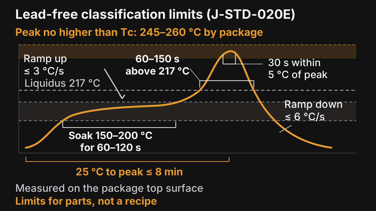
Figure 2. Lead-free classification limits from J-STD-020E as published by Bourns. These bound a profile; they are not a profile to copy.
Revision E, as reproduced by Bourns, gives the same lead-free soak, liquidus, TAL, ramp-down and 8-minute limits, but states the 3 °C/s ramp from the top of the soak (Tsmax) to peak and the 30 seconds as time within 5 °C of the actual peak. If your parts’ datasheets cite a specific revision, read the limits from that revision.
Two notes in the standard’s tables change how you read them. First, the tolerance on peak is one-sided by role: a supplier’s classification run must reach at least Tc, while a user’s production peak must not exceed it. Second, parts intended for lead-free assembly are classified with the lead-free table even if the part itself contains lead. Each measured part has to stay under its own Tc; as a conservative first screen, our suggestion is to plan the profile around the lowest Tc on the bill of materials and then confirm part by part.
Melting points come from the alloy. NIST’s calculated phase diagrams put the tin-lead eutectic at 182.2 °C, the tin-silver-copper ternary eutectic at 215.9 °C and the tin-bismuth eutectic at 138.8 °C. J-STD-020 uses 183 °C and 217 °C as its own reference liquidus values, which is a different basis from NIST’s calculated points. Commercial alloys melt over a range (EFD’s alloy table lists SAC305 at 217 °C solidus and 219 °C liquidus), so take the liquidus for your profile from the paste datasheet. Our guide to choosing solder paste alloys and powder types compares the alloy families.
Common mistake: Programming the J-STD-020 classification curve as the production recipe. It was written to stress-test packages, so running every board at the 260 °C classification peak spends the parts’ entire thermal margin.
Takeaway: Every part must stay under its own Tc and every joint must satisfy the paste’s time above liquidus; everything else is tuning between those two.
How do you set a profile for your board?
You set a profile by working from the paste datasheet and the component limits toward a measured result, in five steps. The aim, in the words of EFD’s profiling guide, is a profile that meets the minimum times at the coolest spot on the board without exceeding the maximum at the hottest spot.
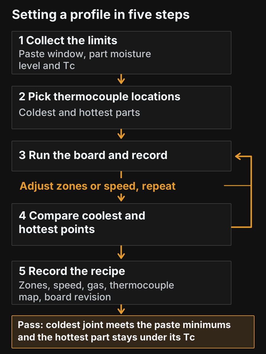
Figure 3. Setting a profile in five steps. The loop between steps 3 and 4 repeats until both the coolest and hottest points sit inside the window.
- Collect the limits. Take the paste datasheet’s profile window (soak, time above liquidus, peak) and the moisture sensitivity level (MSL, the rating that says how long a part may sit outside its dry pack) and Tc of every sensitive part. ACI Technologies stresses checking moisture levels first: a part that has absorbed moisture can crack (“popcorn”) in reflow, and the label on the bag states whether and how long to bake it.
- Pick thermocouple locations. Two measurements answer two questions. A thermocouple on the top of a package checks that part against its Tc. A thermocouple at the joint checks the paste window; for a BGA that means a joint under the package, not the package top. Start with the likely coldest joints (large BGAs, connectors, parts on copper pours) and likely hottest parts (small passives near the board edge), then confirm which are coldest and hottest from the first run. IPC-7530B devotes sections to thermocouple attachment methods and to inner- and outer-row BGA locations because the reading is only as good as the attachment.
- Run the board and record. Use a fully populated board, or a scrap board with the same parts, at the planned conveyor speed.
- Compare coolest and hottest points. Check the coldest joint against the paste’s time above liquidus and the hottest package against its Tc. Adjust zone temperatures or conveyor speed and repeat.
- Record the recipe. Save zone settings, conveyor speed, gas, thermocouple map and the measured curve. IPC-7530B has a section titled “Unique Profile for Each Printed Board Assembly”; our recommendation is to file each recipe against the board revision it was measured on.
If repeated adjustments cannot bring the coldest and hottest points into the window together, check the thermocouple attachment and the paste window first, then the oven’s loading and settings. Only after that is it worth revisiting the oven heating method or the board layout.
Takeaway: A profile is finished when the coldest measured joint meets the paste window and every measured package stays under its Tc.
Which defects trace back to the profile?
Several common reflow defects have profile-related causes, but most also have print, placement, design or material causes that a profile change will not fix. Use the table to decide what to check first before changing oven settings.
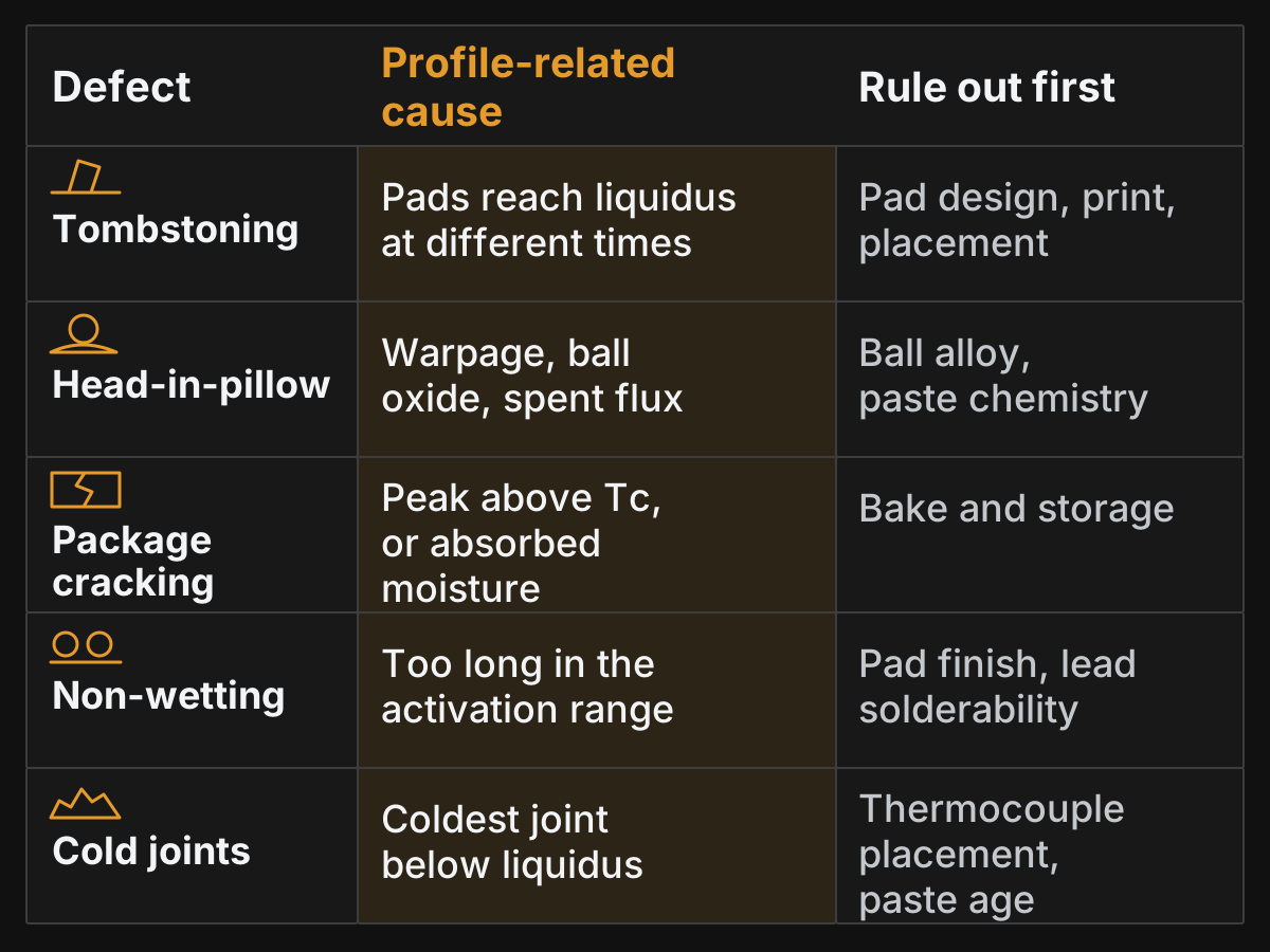
Figure 4. Profile-related causes versus causes to rule out. Compiled from the sources in the table.
| Defect | What you see | Profile-related cause | Rule out first | Source |
|---|---|---|---|---|
| Tombstoning | Chip part stands on one end | Pads reach liquidus at different times (one pad on a copper plane, one on a thin trace) | Pad design, print volume, placement offset, oxidation | EFD, 2005 |
| Head-in-pillow | BGA ball sits in paste but is not fused; often passes functional test | Package warps during heating, ball oxidises, flux is spent by the time solder melts | Ball alloy, paste chemistry | Seelig (AIM), 2009 |
| Package cracking (“popcorning”) | Cracked or delaminated package | Peak too high for the part, or moisture absorbed beyond its rating | Bake and storage per moisture level | J-STD-020; ACI, 2019 |
| Non-wetting or de-wetting | Solder beads up or pulls back from the pad | Too long in the activation range, flux exhausted | Pad finish and component lead solderability | EFD profiling guide |
| Cold or incomplete joints | Paste not fully melted, joint not formed | Coldest joint below liquidus or too little time above it (derived from the definitions) | Thermocouple placement, paste condition | Derived |
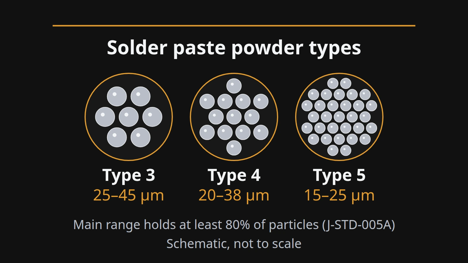
IPC-7530B’s troubleshooting chapter also covers voids, bridging, solder balls, solder beading, grainy solder and wicking; we have not listed causes for those here because we only have its contents page. ACI’s tip adds a practical rule: once the printer and placement machine are set up properly, recurring shifts and mid-chip solder balls point to the oven profile rather than another factor. The reverse also holds: on a poorly printed board, profile changes chase symptoms, so check powder type against stencil aperture size before touching the oven.
Head-in-pillow deserves special mention because it is easy to miss. Seelig’s paper notes that the joint can carry current well enough to pass functional test and then fail in the field under mechanical or thermal stress, so agree an inspection method for hidden BGA joints with your assembler rather than relying on functional test.
Takeaway: Fix print and placement first, then use the profile table to target the defects that actually have thermal causes.
What changes for small-batch and hobby reflow?
The same limits apply to a benchtop oven, a converted toaster oven or a hot plate: the paste window still sets the minimum and each part’s Tc still sets its maximum. What changes is control. Small ovens often have one heating zone and no conveyor, so the profile is a time-based program rather than a set of zones. The controller reads its own sensor, not your board; the oven’s manual says where that sensor sits.
That gap is why a thermocouple on the board matters even for one-off prototypes. Taping a thermocouple to a representative part shows whether the board reached liquidus long enough and whether the hottest small part stayed under its rating. Without it, a “profile” is a guess.
A hot plate heats from below through the board. Our suggestion is to use it only for single-sided boards that lie flat on the plate; parts on the underside would sit on the heater unless a fixture holds the board clear. For which oven formats suit prototype runs, see our benchtop and conveyor oven comparison.
Treat any oven used for solder paste as dedicated equipment and check the paste’s safety data sheet; tin-lead paste contains lead, so we do not suggest returning such an oven to food use.
Takeaway: Small ovens change the controls, not the limits; measure on the board before trusting the controller’s number.
When this does not apply
This page describes convection-style reflow of surface-mount assemblies with standard tin-lead or tin-silver-copper paste. Check the specific guidance instead in these cases:
- Vapor-phase reflow. The assembly is heated by condensing vapour and cannot exceed the boiling point of the heat-transfer fluid. Illés and colleagues’ review notes that the fast heating raises its own risks for moisture-sensitive packages. The four-stage logic still applies, but the controls differ; our oven guide covers vapor-phase equipment.
- Low-temperature alloys. Tin-bismuth pastes melt near 138 °C and use a different window; IPC-7530B includes a separate profile comparison for SnBi and resin-containing SnBi pastes.
- Wave and selective soldering. These melt solder in a bath or nozzle rather than on the board. See our comparison of wave, reflow, selective and hand soldering.
- Mixed tin-lead and lead-free parts. Lead-free BGAs on a tin-lead line need a deliberate profile decision; IPC-7530B covers backward-compatibility profiles.
- Class 3 and contract requirements. IPC J-STD-001 and the customer’s drawing can impose requirements beyond the paste datasheet.
Takeaway: If the heat source, the alloy or the contract changes, go back to the matching document before reusing a profile.
Method and sources
Compiled on 7 October 2026 from public documents; nothing here comes from our own testing. J-STD-020 values are taken from component makers’ published reproductions of the standard’s tables (Bourns for revision E, Cypress/Infineon for revision D.1); we did not read the full standard. IPC-7530B is cited from its published table of contents only. Melting points are NIST calculated values. Defect mechanisms come from the named technical papers, which are written by training centres and material suppliers; we use them for mechanisms, not for supplier-specific settings. Sources are listed at the end of the page.
Related reading
- Reflow oven types and how to choose one — Compare heating methods and oven formats before buying.
- How to choose solder paste — Match powder type and alloy to the stencil and the profile.
- Wave vs reflow vs selective vs hand soldering — Decide which process each part on a mixed board needs.
- All electronics manufacturing articles — Browse the rest of the SMT and soldering explainers.