In IPC-HDBK-830A Section 1.3 Scope, conformal coating is defined as a thin, transparent, polymeric coating, with typical coating thickness ranging from 12.5 µm [0.49 mil] to 200 µm [7.9 mil]. In IPC-HDBK-830A Figure 7-5, a ‘4’ adhesion rating means the film cannot be removed with the pick and the force required to move the film typically damages the underlying substrate.
Planning how to remove conformal coating in electronics manufacturing rework starts with resin identification and procedure selection. For base polymer comparisons and film thickness checks on new assemblies, see our companion guide on conformal coating for PCBs, thickness and rework.
Standardized Coating Removal Procedures and Pad Repair Boundaries
IPC-7711B/7721B Procedure 2.3.1 covers Coating Removal, Identification of Conformal Coating for board types R, F, W, C at an Advanced skill level and High level of conformance. IPC-7711B/7721B Procedure 2.3.2 covers Coating Removal, Solvent Method for board types R, F, W, C at an Advanced skill level and High level of conformance. IPC-7711B/7721B Procedure 2.3.3 covers Coating Removal, Peeling Method for board types R, F, W, C at an Advanced skill level and High level of conformance.
IPC-7711B/7721B Procedure 2.3.4 covers Coating Removal, Thermal Method for board types R, F, W, C at an Advanced skill level and High level of conformance. IPC-7711B/7721B Procedure 2.3.5 covers Coating Removal, Grinding/Scraping Method for board types R, F, W, C at an Advanced skill level and High level of conformance. IPC-7711B/7721B Procedure 2.3.6 covers Coating Removal, Micro Blasting Method for board types R, F, W, C at an Advanced skill level and High level of conformance.
IPC-7711B/7721B lists Lifted Land Repair procedures 4.4.1 (Epoxy Method) and 4.4.2 (Film Adhesive Method) for board types R, F at an Advanced skill level and Medium level of conformance. IPC-7711B/7721B lists Surface Mount Pad Repair procedures 4.7.1 (Epoxy Method, Medium conformance), 4.7.2 (Film Adhesive Method, High conformance), and 4.7.3 (BGA Pad Repair, Film Adhesive Method, High conformance) for board types R, F, C.
| Procedure | Title and Rework Scope | Board Types | Skill and Conformance Level |
|---|---|---|---|
| 2.3.1 | Coating Removal, Identification of Conformal Coating | R, F, W, C | Advanced skill level, High level of conformance |
| 2.3.2 | Coating Removal, Solvent Method | R, F, W, C | Advanced skill level, High level of conformance |
| 2.3.3 | Coating Removal, Peeling Method | R, F, W, C | Advanced skill level, High level of conformance |
| 2.3.4 | Coating Removal, Thermal Method | R, F, W, C | Advanced skill level, High level of conformance |
| 2.3.5 | Coating Removal, Grinding/Scraping Method | R, F, W, C | Advanced skill level, High level of conformance |
| 2.3.6 | Coating Removal, Micro Blasting Method | R, F, W, C | Advanced skill level, High level of conformance |
| 4.4.1 and 4.4.2 | Lifted Land Repair, Epoxy Method (4.4.1) and Film Adhesive Method (4.4.2) | R, F | Advanced skill level, Medium level of conformance |
| 4.7.1, 4.7.2, and 4.7.3 | Surface Mount Pad Repair: Epoxy Method (4.7.1), Film Adhesive Method (4.7.2), and BGA Pad Repair, Film Adhesive Method (4.7.3) | R, F, C | Advanced skill level; Medium (4.7.1) and High (4.7.2, 4.7.3) conformance |
Solder Mask Qualification Classes and Post-Soldering Chemical Compatibility
IPC-SM-840E Section 1.3 provides four classes of solder mask and cover material requirements—T, FT, H, and FH—and specifies that qualification to a particular class shall not be extended to cover any other class. IPC-SM-840E states that determining compatibility between solder mask and cover materials and post soldering products and processes is beyond the scope of the specification, and requirements to do so shall be as agreed between user and supplier (AABUS).
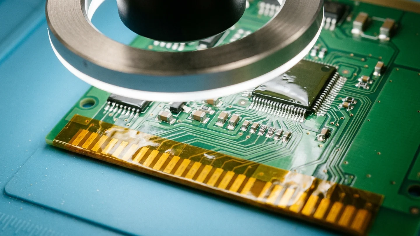
Chemical Stripping by PCB Coating Types: Acrylic, Polyurethane, Silicone, and Parylene
Matching a chemical conformal coating remover to specific PCB coating types follows the cured resin properties and material compatibility boundaries published by the formulation manufacturer. For automated selective dispensing valve setup and wet-to-dry film build control prior to curing, consult our guide on conformal coating machine selection and film-build control.
Solvent-Based Acrylic Coating and Stripper Specifications
For HumiSeal 1B31 cured acrylic conformal coating, the recommended coating thickness is 25 - 75 microns and the recommended stripper is HumiSeal Stripper 1080, 1080EU. HumiSeal Stripper 1080 is compatible with HumiSeal Solvent Based Acrylics and has a relative evaporating rate (BuAc=1) of 1.0, specific gravity of 1.3 ± 0.02, and flash point (TCC) of 21.7 °C.
HumiSeal Stripper 1080 is safe for use on epoxy markings, epoxy substrates, solder, copper, silver, gold and nickel plating, and it will swell or dissolve polystyrene and vinyl. Directions for use of HumiSeal Stripper 1080 specify soaking the assembly for 30-60 minutes, cleaning with IPA or DI water, and baking for a minimum of 30 minutes at 60 - 65°C after the final cleaning process.
Crosslinked Polyurethane and Silicone Stripping Specifications
For HumiSeal 1A33 cured urethane conformal coating, the recommended coating thickness is 25 - 75 microns and the recommended stripper is HumiSeal Stripper 1063. HumiSeal Stripper 1063 is compatible with HumiSeal 1A27 and 1A33 polyurethane coating families and has a relative evaporating rate (BuAc=1) of 2.10, specific gravity of 0.82 ± 0.01, flash point (TCC) of 11.1 °C, and shelf life of 12 months.
HumiSeal Stripper 1063 is safe for use on copper, gold, silver or nickel plating, amine cured epoxies, and Teflon, and it will attack anhydride-cured epoxies and some magnetic wire coatings. A fully cured polyurethane coating of nominal thickness will typically dissolve readily within 60 minutes upon contact with HumiSeal Stripper 1063, addition of heat between 40 – 45°C can aid stripping efficiency, and following cleaning the assembly should be baked for a minimum of 30 minutes at 60 – 65°C.
For HumiSeal 1C49 silicone conformal coating, the recommended coating thickness is 50 - 200 microns and the recommended stripper is HumiSeal Stripper 1091.
| Coating or Stripper Scope | Published Physical or Thickness Parameters | Compatibility, Soak, or Post-Bake Parameters |
|---|---|---|
| HumiSeal 1B31 Cured Acrylic | Recommended coating thickness 25 - 75 microns | Recommended stripper HumiSeal Stripper 1080, 1080EU |
| HumiSeal Stripper 1080 Physical Properties | Compatible with HumiSeal Solvent Based Acrylics; Relative Evaporating Rate (BuAc=1) 1.0 | Specific Gravity 1.3 ± 0.02; Flash Point (TCC) 21.7 °C |
| HumiSeal Stripper 1080 Material Compatibility | Safe for use on epoxy markings, epoxy substrates, solder, copper, silver, gold and nickel plating | Will swell or dissolve polystyrene and vinyl |
| HumiSeal Stripper 1080 Process Schedule | Soak for 30-60 minutes; clean with IPA or DI water | Bake for a minimum of 30 minutes at 60 - 65°C after final cleaning |
| HumiSeal 1A33 Cured Urethane | Recommended coating thickness 25 - 75 microns | Recommended stripper HumiSeal Stripper 1063 |
| HumiSeal Stripper 1063 Physical Properties | Compatible with 1A27 and 1A33 families; Relative Evaporating Rate (BuAc=1) 2.10 | Specific Gravity 0.82 ± 0.01; Flash Point (TCC) 11.1 °C; Shelf life 12 months |
| HumiSeal Stripper 1063 Material Compatibility | Safe for use on copper, gold, silver or nickel plating, amine cured epoxies, and Teflon | Will attack anhydride-cured epoxies and some magnetic wire coatings |
| HumiSeal Stripper 1063 Process Schedule | Fully cured polyurethane of nominal thickness typically dissolves readily within 60 minutes; heat between 40 – 45°C can aid efficiency | Bake for a minimum of 30 minutes at 60 – 65°C following cleaning |
| HumiSeal 1C49 Silicone | Recommended coating thickness 50 - 200 microns | Recommended stripper HumiSeal Stripper 1091 |
Why Chemical Stripping Is Not Recommended for Parylene
Specialty Coating Systems (SCS) states that Tetrahydrofuran (THF) requires approximately 3 hours of immersion to aid in the delamination of a Parylene layer, that Benzolyl benzoate and chloronaphthalene above 150°C are also known to remove Parylene, and that chemical removal of Parylene is not a recommended process. Specialty Coating Systems (SCS) states that laser ablation, reactive ion etching (oxygen plasma), and micro-abrasion are the best options for the removal of Parylene.
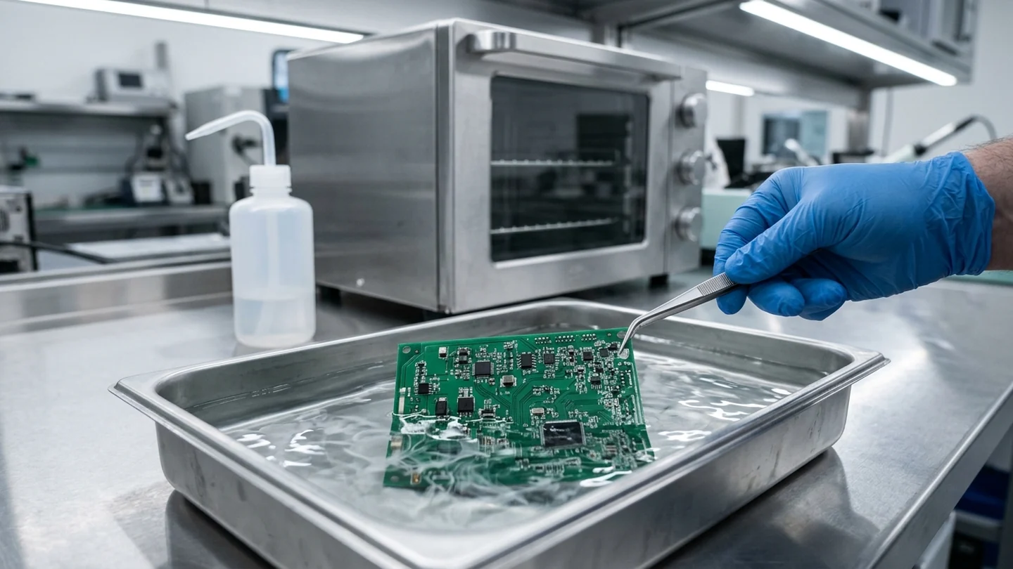
Micro-Abrasive Blasting Parameters, Media Hardness, and ESD Grounding
Comco Application Notes state that most conformal coating removal applications use round nozzles with openings ranging from .018“ to .060“, walnut shell has a 250μ particle size, and plastic media has a 200μ particle size. Comco Application Notes state that when removing coatings from around a very small device, the operator will typically hold the nozzle 1/4“ from the surface for maximum control.
Matching Blast Media and Pressure to Coating Chemistry
Comco wheat starch abrasive media registers as a 2 on the Mohs scale, has an average particle size of 0.004“ or 100 µ, and has a blocky and crystalline particle shape with shard-like edges. Comco states that wheat starch abrasive media is too mild to present any real risk of damage to the solder mask or underlying components and is water soluble and biodegradable. In Comco’s demonstrated example of removing a thin layer of silicone conformal coating, 100 µ wheat starch was blasted at 50-60 psi through a 0.030“ conductive nozzle.
Comco states that plastic media quickly removes parylene and thick coatings, is slightly harder than wheat starch with particles smaller than walnut shell, and is treated to reduce electrostatic discharge.
In the Comco Application Notes parameter table for conformal coating removal, Acrylic is listed at 50 PSI blast pressure with Walnut Shell recommended powder, and Epoxy is listed at 40 PSI with Sodium Bicarbonate. In the Comco Application Notes parameter table for conformal coating removal, Silicone is listed at 35 PSI with Sodium Bicarbonate, Parylene at 30 PSI with Sodium Bicarbonate, and Polyurethane at 40 PSI with Sodium Bicarbonate. In the Comco Application Notes parameter table for conformal coating removal, UV Epoxy and UV Silicon are each listed at 50 PSI blast pressure with Plastic recommended powder.
| Micro-Abrasive Parameter Scope | Published Media, Pressure, or Nozzle Specification | Published Secondary Specification or Control |
|---|---|---|
| Acrylic and Epoxy Blast Parameters | Acrylic: 50 PSI blast pressure with Walnut Shell recommended powder | Epoxy: 40 PSI blast pressure with Sodium Bicarbonate recommended powder |
| Silicone, Parylene, and Polyurethane Blast Parameters | Silicone: 35 PSI with Sodium Bicarbonate; Parylene: 30 PSI with Sodium Bicarbonate | Polyurethane: 40 PSI with Sodium Bicarbonate recommended powder |
| UV Epoxy and UV Silicon Blast Parameters | UV Epoxy: 50 PSI blast pressure with Plastic recommended powder | UV Silicon: 50 PSI blast pressure with Plastic recommended powder |
| Comco Wheat Starch Media Properties | Registers as a 2 on the Mohs scale; average particle size 0.004“ or 100 µ | Blocky and crystalline particle shape with shard-like edges |
| Comco Thin Silicone Blasting Example | 100 µ wheat starch media blasted at 50-60 psi | Directed through a 0.030“ conductive nozzle to remove a thin layer of silicone |
| Comco Nozzle Openings and Media Particle Sizes | Most conformal coating removal applications use round nozzles with openings ranging from .018“ to .060“ | Walnut shell: 250μ particle size; Plastic media: 200μ particle size |
| Small-Device Nozzle Standoff | Removing coatings from around a very small device | Operator will typically hold the nozzle 1/4“ from the surface for maximum control |
ESD Grounding, Desiccant Air Drying, and HEPA Filtration
In the Comco ProCenter Plus ESD system, the edge conductor grounding bar is made of conductive rubber material to ground all edge pins on boards with edge connectors, and the needle probe pierces through the coating to ground a target trace. On the Comco ProCenter Plus workstation, the desiccant air dryer uses silica gel desiccant beads that absorb moisture to dew points as low as -25°F at flow rates up to 7.5 SCFM, and HEPA air filtration removes 99.97% of all particles greater than 0.3 micron in size.
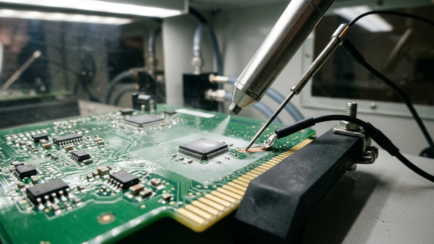
Thermal and Mechanical Coating Removal Risks on Populated PCBs
Specialty Coating Systems (SCS) states that in thermal conformal coating removal, the test temperature is elevated from room temperature to approximately 100°C and can be increased gradually if needed while watching component thermal limitations. Specialty Coating Systems (SCS) states that for Thermal Removal (Procedure 2.3.4), the very high temperatures required can generate delamination/discoloration, overheat temperature-sensitive components, damage solder joints, and leave surface residue.
Specialty Coating Systems (SCS) states that mechanical removal techniques (Procedure 2.3.5) include grinding, scraping, cutting, or sanding coating from the surface, require thorough masking of non-removal surfaces, and that poor mechanical removal processing can accelerate damage to the coating/PCB. When components are desoldered and replaced after localized coating removal, compare board heat exposure against the assembly thermal envelopes covered in our guide on wave vs reflow soldering.
Pre-Rework Conformal Coating Removal Checklist
Review and record the following parameters before running conformal coating removal on a populated assembly:
- Coating identification and rework procedure: Confirm the polymer family under IPC-7711B/7721B Procedure 2.3.1 (Coating Removal, Identification of Conformal Coating) for board types R, F, W, C at an Advanced skill level and High level of conformance.
- Target surface-mount and BGA pad repair boundaries: Identify whether the rework zone involves lands governed by IPC-7711B/7721B Surface Mount Pad Repair procedures 4.7.1 (Epoxy Method, Medium conformance), 4.7.2 (Film Adhesive Method, High conformance), and 4.7.3 (BGA Pad Repair, Film Adhesive Method, High conformance) for board types R, F, C.
- Solder mask qualification class and chemical compatibility: Verify the solder mask class under IPC-SM-840E Section 1.3 (T, FT, H, and FH, where qualification to a particular class shall not be extended to cover any other class).
- Workstation ESD grounding, air drying, and HEPA filtration: Ground edge connector pins with a conductive rubber edge conductor grounding bar and pierce the coating with a needle probe to ground a target trace on the Comco ProCenter Plus ESD system.
Sources
- IPC — IPC-7711B/7721B Rework, Modification and Repair of Electronic Assemblies
- IPC — IPC-HDBK-830A Guidelines for Design, Selection and Application of Conformal Coatings
- IPC — IPC-SM-840E Qualification and Performance Specification of Permanent Solder Mask and Flexible Cover Materials
- HumiSeal (Chase Corporation) — HumiSeal 1B31 Acrylic Conformal Coating Technical Data Sheet
- HumiSeal — HumiSeal Stripper 1080 Technical Data Sheet
- HumiSeal (Chase Corporation) — HumiSeal 1A33 Urethane Conformal Coating Technical Data Sheet
- HumiSeal — HumiSeal Stripper 1063 Technical Data Sheet
- HumiSeal (Chase Corporation) — HumiSeal 1C49 Silicone Conformal Coating Technical Data Sheet
- Comco Inc. — Removing Conformal Coating: Consider Wheat Starch
- Comco Inc. — Conformal Coating Removal Application Guide
- Comco Inc. — Application Notes: Conformal Coating Removal (App-Notes-CCR)
- Specialty Coating Systems (SCS) — Removing Conformal Coatings
- Specialty Coating Systems (SCS) — Conformal Coating Removal Standards