Using one conformal coating thickness for every chemistry can turn a finished PCB into rework through inadequate protection or excess film that bubbles, cures poorly, or cracks under thermal shock. Choose the exact formulation, its published thickness recommendation and its removal route together. HumiSeal 1B31 acrylic and 1A33 polyurethane each specify 25–75 µm in their cured-coating tables; 1C49 silicone specifies 50–200 µm recommended coating thickness, with no explicit wet-or-dry label in that row. That distinction determines what a thickness reading can establish. Sources: HumiSeal thickness guidance, 1B31 TDS, 1A33 TDS, 1C49 TDS.
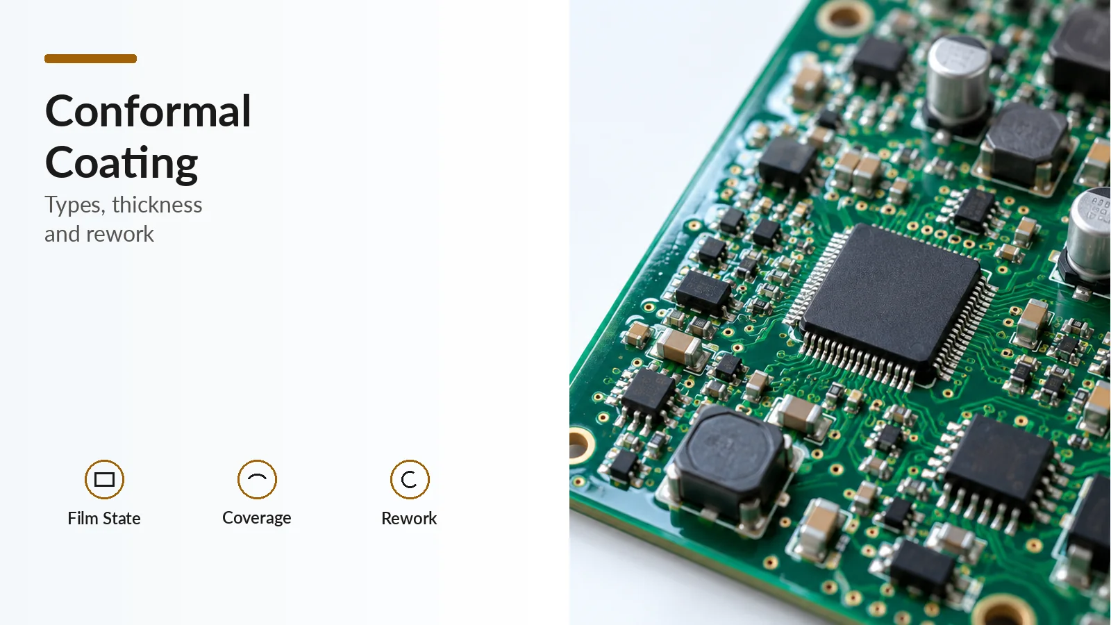
Conformal coating is a thin polymer layer applied to a printed circuit assembly for protection from its service environment. The practical decision is a material-and-process combination: exposure, assembly compatibility, local coverage, measurement access and later repair all matter. This guide compares three named formulations and sets out a verification record for the populated board. The IPC-HDBK-830A public excerpt, §1.3, makes end-use suitability testing part of that selection.
Which conformal coating type fits the exposure and repair plan?
Start with the service requirement, then evaluate a formulation with documented thickness and removal guidance. The examples below support different selection questions; their published properties do not establish a chemistry-wide ranking.
| Type and named example | Reason to evaluate it | Published thickness and measurement state | Recommended removal product | Dominant Failure Mode & Prevention |
|---|---|---|---|---|
| Acrylic — HumiSeal 1B31 | A documented acrylic option when the coating and later removal route must both be specified | 25–75 µm cured, in the cured-coating properties table | HumiSeal Stripper 1080 | Thin corners can remain poorly protected. Verify local coverage and assembly cleanliness compatibility alongside flat-area thickness. |
| Polyurethane — HumiSeal 1A33 | The manufacturer lists chemical resistance; evaluate it against the actual fluid exposure | 25–75 µm cured, in the cured-coating properties table | HumiSeal Stripper 1063 | Pooling can leave poorly cured film. Check inside corners and tight component gaps; test suitability for the actual exposure. |
| Silicone — HumiSeal 1C49 | A moisture-curing formulation described as flexible and repairable | 50–200 µm recommended coating thickness; the TDS row does not label wet or dry | HumiSeal Stripper 1091 | Conventional spray equipment can create bubbles. Use equipment designed for high-viscosity coating and trial it before production. |
The thickness and stripper entries come from the 1B31, 1A33 and 1C49 technical data sheets. Corner and pooling mechanisms follow HumiSeal’s uniformity guidance. These are prevention priorities to verify on the assembly, rather than comparative failure-rate data.
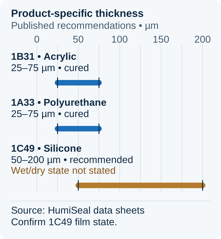
The intervals belong to the named products. Confirm the measurement state for 1C49 before using its range as a cured-film production criterion.
Specify the removal product when planning repair, then establish its compatibility with the actual assembly and the removal/recoating procedure. A named stripper recommendation alone does not supply a soak time, a universal solvent substitute or permission to expose every board material to it.
How much conformal coating is enough?
Use the exact product recommendation and an agreed measurement state. The August 2013 IPC-HDBK-830A excerpt describes a typical overall envelope of 12.5–200 µm. It is a broad description of conformal coating, not a target or a chemistry-specific acceptance interval. Its scope also states that processing and cure depend on chemistry and that suitability must be established for the intended application.
Rules-of-Thumb
- For HumiSeal 1B31 acrylic or 1A33 polyurethane, a cured reading below 25 µm or above 75 µm is outside that product’s published recommended interval. Investigate the process against the agreed assembly requirements.
- For HumiSeal 1C49 silicone, retain 50–200 µm as “recommended coating thickness” until the supplier confirms the wet/dry interpretation for the production specification.
- Keep the handbook’s broad envelope separate from product-specific limits. Assess corner coverage and pooling separately from an accessible flat-area reading.
A simple interval calculation can show how close a reading lies to the nearest recommended boundary:
Interval margin = min(measured thickness − lower recommendation, upper recommendation − measured thickness).
For an explicitly hypothetical HumiSeal 1B31 cured-film reading of 50 µm, the margin is min(50 − 25, 75 − 50) = 25 µm. This is arithmetic distance to the published bounds. It does not include measurement uncertainty or establish cure, electrical performance or end-use suitability.
Why do corners and cleanliness need separate checks?
A populated board can have acceptable film on an accessible flat region while top corners have less coverage and inside corners accumulate excess. HumiSeal describes liquid coating flowing off vertical surfaces and pooling between closely spaced components. Excess build can bring insufficient cure and cracking risk; too little film can leave inadequate protection. Source: HumiSeal’s coating-uniformity guidance.
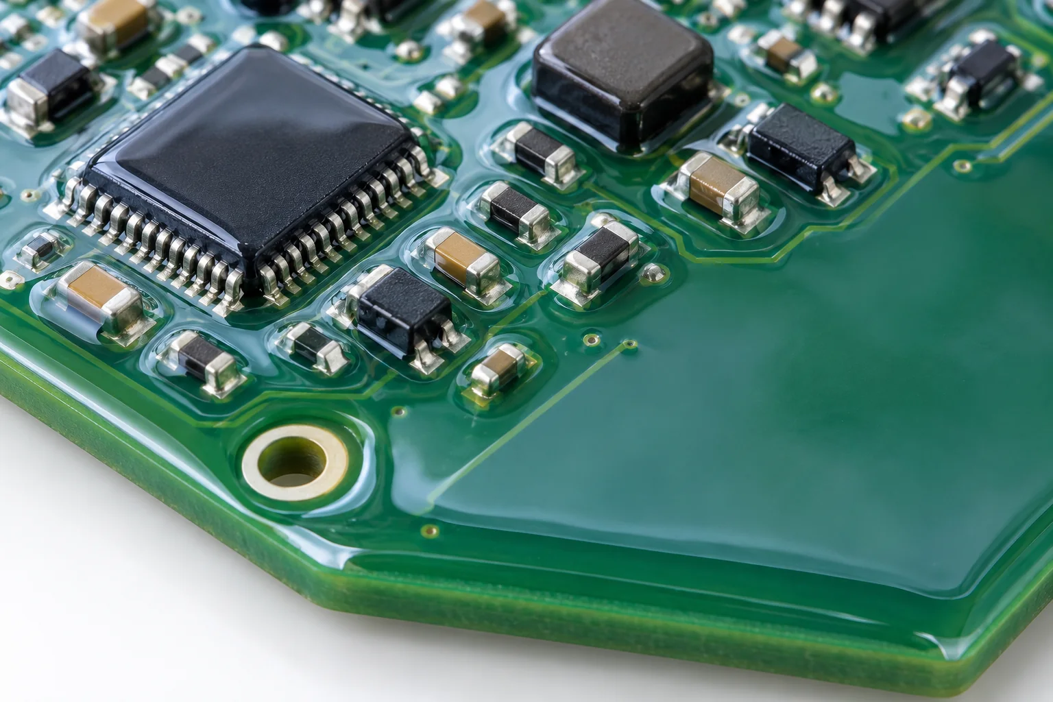
Treat vertical faces, top corners and tight gaps as separate inspection locations. Multiple thinner layers are one possible response to uneven build, provided the exact coating’s recoat and cure instructions support that approach. For 1C49, follow its specific spray guidance: equipment designed for high-viscosity coatings, a trial before production, and no thinner, which its TDS does not recommend.
Cleanliness is also a compatibility question. The 1B31 and 1A33 application sections call for testing with the actual assembly materials, process conditions and cleanliness level, including low-residue “no-clean” assemblies. A no-clean designation therefore does not settle coating compatibility. Record the assembly condition after reflow soldering as an input to that assessment. Sources: 1B31 application guidance, 1A33 application guidance.
How should coating thickness be measured on the board?
Separate the wet-film process check from the cured-film result
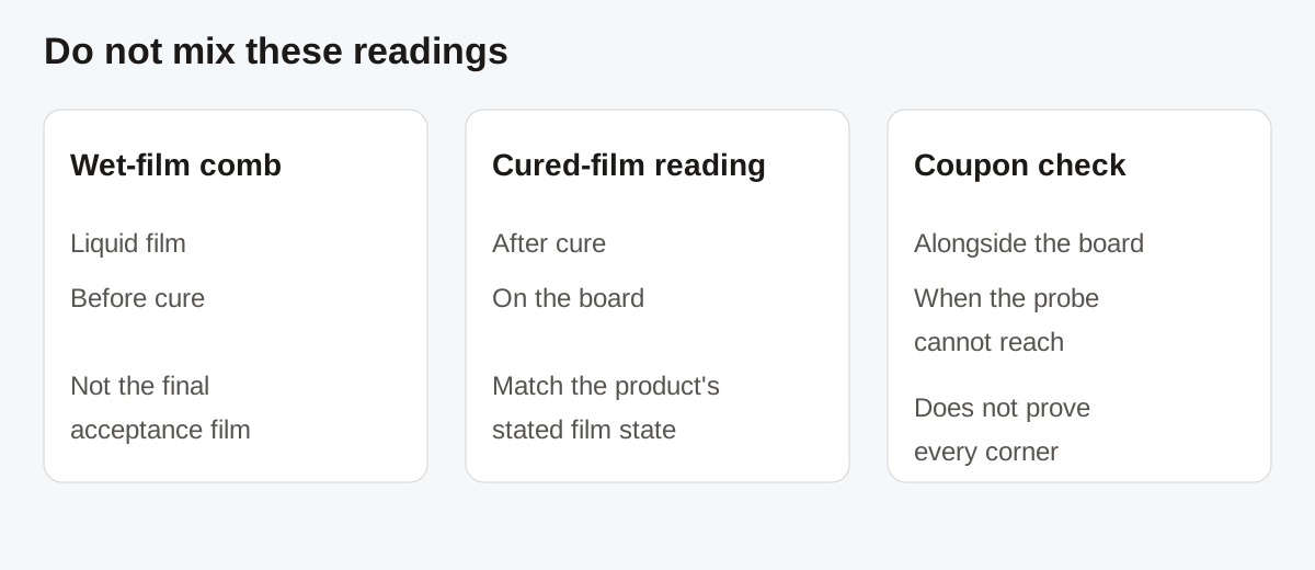
A wet-film comb brackets the liquid film between the last tooth that becomes coated and the next tooth that stays uncoated. HumiSeal’s illustrated 100–120 µm wet interval demonstrates that reading method; it is not an application target for the products above. Record it as a wet interval, then verify the film state required by the product and assembly specification. Source: HumiSeal wet-gauge guide.
Do not calculate cured thickness by multiplying a wet reading by a datasheet’s weight-percent solids. A weight fraction does not establish the volume ratio needed for that conversion.
Select the method from substrate and probe access
DeFelsko identifies substrate construction, available unpopulated area and the coating’s thickness range as measurement-selection inputs. Its PCB measurement guide supports these routes:
- Accessible area over a copper ground plane: use a suitable eddy-current gauge. Measure directly over the ground plane in an unpopulated region, and zero on the uncoated solder-mask surface before measuring coating thickness.
- Board without a suitable ground plane: evaluate an ultrasonic method for that particular layer structure. DeFelsko warns that solder mask and PCB layers can produce false readings; ultrasound needs application validation.
- No probe access: coat a metal coupon alongside the PCB and measure it as a substitution. Nonferrous coupons use an eddy-current method; ferrous coupons use a magnetic method.
Keep coupon results explicitly identified. Combining DeFelsko’s substitution method with HumiSeal’s coverage guidance means that a coupon result still needs a separate, agreed way to verify local board coverage. A coupon cannot reproduce every component corner and gap.
What should the coating process record contain?
Use the following as a practical record built from the material and measurement guidance above:
- Material and requirement: record the exact formulation, board revision, required interval, film state and applicable cure instructions. Resolve the 1C49 thickness-state question before writing a cured-film criterion.
- Assembly compatibility: identify the materials, cleanliness condition and process evaluated for coating compatibility.
- Measurement map: identify accessible board locations, the substrate beneath them, gauge method and zeroing surface. Label any separately coated coupon results.
- Local coverage: record the checks on vertical faces, top corners and pooled regions separately from flat-area thickness.
- Repair route: record the product-specific remover and the established assembly-compatible procedure, then repeat the relevant coverage and thickness verification after recoating.
For process-cost planning, track the effort that selection can shift: cleaning and masking labor, coating passes, cure capacity, inspection access, removal, recoating and repeat measurement. This qualitative ledger helps compare complete process routes without assigning unsupported prices or savings.
The useful output is a material-and-verification record: named coating, correctly labeled thickness recommendation, documented repair route and evidence from the relevant board locations. Related assembly guides are collected under electronics manufacturing.