Clearing the reset flags before you copy them wastes the only record of which watchdog, or which other source, restarted the processor. Save that register at the first point in main you control, then run a no-refresh spin with the debug probe disconnected.
These notes were compiled on 14 October 2026 from public ST and FreeRTOS pages saved on 11 October 2026. No board was reset for this page, and no timeout was copied from one STM32 series onto another.
The independent watchdog and the window watchdog are different resets. Save the reset-flag register at the first point in main you control, clear it only after that copy, and then start the watchdog under test without refreshing it while the debug probe is disconnected. Pavel A. wrote to start the IWDG, stop refreshing it, and let the core spin. His reply, marked Best answer on 5 January 2023, reads RCC->CSR on a Nucleo-L476RG thread and tests RCC_CSR_IWDGRSTF, RCC_CSR_WWDGRSTF, and RCC_CSR_SFTRSTF. Those three names belong to that reply. Copy the flag names from the reference manual for the MCU in front of you, and leave the cell blank until you have. The ST wiki Getting started with WDG, approved 4 September 2026, says either counter can be frozen in debug mode, and that a watchdog, once enabled, is disabled only by a reset. The L476 ranges on that wiki are an example for STM32L476xx. They are not a timeout for every STM32.
Scroll the log sideways on a phone. Copy one row per restart you care about. Leave every cell blank until the manual, the option bytes, or the run in front of you fills it. A blank cell is an unknown. It is not zero, and it is not a default timeout.
| MCU and board | Watchdog started | Flag value saved before clear | Probe attached | Freeze-in-debug, from this manual | Last refresh, and what blocked it | No-refresh result, and which flag |
|---|---|---|---|---|---|---|
An unlabeled green board beside a blank card and a black pen.
Other notes in this category are on the Embedded Systems page. The pin choice for the probe is a separate record on the JTAG and SWD header checklist. This log sits on the article index.
What do you copy before the flags are cleared?
The first row is the job. MM..1 wrote, on 4 January 2023, to read the reset flags at the start of main and clear them. Pavel A.’s reply the next day is the read: assign RCC->CSR to a variable, then test the three flags in that reply. Clear only after the variable, and a log line, hold the value. A later read, after some other startup code has cleared the register, cannot reconstruct it.
Pavel’s reply, for the Nucleo-L476RG question opened in STM32CubeIDE 1.11.0, is this test:
uint32_t reset_flags = RCC->CSR;
if (reset_flags & RCC_CSR_IWDGRSTF) {
  /* This was IWDG */
} else if (reset_flags & RCC_CSR_WWDGRSTF) {
  /* This was WWDG */
} else if (reset_flags & RCC_CSR_SFTRSTF) {
  /* Software reset (NVIC_SystemReset or by debugger) */
}
Write the raw value as well as the branch you took. The three symbols are the ones his reply names. If the header for your part uses different names, his snippet is not your map. This page does not add flag bits he did not name.
The 4 January 2023 question also pasted a six-step key-register sequence for an IWDG with the window option disabled, including a refresh write of 0xAAAA. This page does not repeat that sequence as a setup recipe. Take the enable, the prescaler, and the reload from the reference manual for the part you are building. The wiki, in the IWDG section, states the same refresh key: write 0xAAAA to the key register to reload the counter. Pain, on the FreeRTOS thread, wrote both IWDG->KR = 0xAAAA and HAL_IWDG_Refresh.
Takeaway: Copy the flag register, then clear it. A clear register at the end of main is not evidence.
How do you tell an IWDG flag from a WWDG flag?
Use the branch you saved, and keep the two watchdogs on separate rows. The wiki, approved 4 September 2026 and retrieved as oldid 90007, defines them as different blocks.
| Item | What that wiki page states | What you write on your log |
|---|---|---|
| WWDG | 7-bit downcounter, clocked from the main clock, early-warning interrupt, counter can be frozen in debug mode. A reload that is too early or too late initiates a reset. | Which of those behaviors your manual still states for this part |
| WWDG example range | For example, STM32L476xx, 51.2 µs to 28.2 ms | Blank, unless this part is that device and the current manual still prints this range |
| WWDG demo | NUCLEO-L476RG. Prescaler 8, window 80, downcounter 128. HCLK entered as 80 MHz. The comment next to HAL_Delay(20) is (1/80000000)40968*(127-80+1) ~ 20 ms | Do not copy the 20 ms delay onto another clock |
| IWDG | 12-bit downcounter, 8-bit prescaler, independent 32 kHz LSI, runs in Stop and Standby, counter can be frozen in debug mode. Can also be a free-running timer. | The clock your manual names. LSI here is the wiki’s clock, not a measured frequency |
| IWDG example range | For example, STM32L476xx, 125 µs to 32.7 s | Blank, unless this part is that device and the current manual still prints this range |
| IWDG demo | NUCLEO-L476RG. Prescaler 128, window 100, reload 100. The page sets the window equal to the downcounter “to define the widest window.” It calculates 32000/128 = 250 Hz, 4 ms per tick, and 0.004 × 100 = 400 ms, then uses HAL_Delay(300) | That 400 ms ceiling belongs to those inputs. It is not your reload |
| IWDG count | On start, the 12-bit counter counts down from 0xFFF. The key 0xAAAA reloads it. Reaching 0x000 generates a system reset | Confirm the start value and the key in your manual before you treat them as yours |
| Disable | Option bytes can start the watchdog in hardware or software. Once enabled, it can only be disabled by a reset | Record hardware or software start. Do not turn the watchdog off to “finish” the test |
Pavel’s if / else if chain reports one branch. A part that sets more than one flag in the same restart needs the raw value on the log, because the first true test in that chain hides the others. His reply does not say the flags are mutually exclusive on every STM32.
Takeaway: An IWDG flag and a WWDG flag are different rows. The L476 demo numbers stay on the L476 row.
What does a no-refresh spin show when the probe is off?
Pavel A. wrote to start the IWDG, stop refreshing it, and let the core spin. He wrote “for a few minutes,” and that the MCU should reset. “A few minutes” is his instruction on that thread. It is not a timeout from a reference manual. The L476 wiki example above calculates a 400 ms ceiling for its own IWDG reload, so a reset on that demo can arrive long before a few minutes. Use the ceiling in the manual for your prescaler, your clock, and your reload. Leave the cell blank when that page is not open.
Run the spin twice and write both results.
- Start only the watchdog you are trying to prove. Leave the other one off unless the option bytes already started it. If hardware start is on, write that, and do not claim you started it in main.
- Remove the refresh. A loop that still calls the refresh, or still calls a delay that the project uses as the feed, is not this test.
- With the probe attached, record whether a reset happens and which flag you saved on the way back up.
- Disconnect the probe and repeat. The wiki says the counter can be frozen in debug mode. A spin that sits there while the probe is attached does not show that the watchdog is off.
- On the way back up, read the copy you saved in the first section. IWDG flag means the branch Pavel labeled IWDG. WWDG flag means the branch he labeled WWDG. The software-reset flag is his third branch: NVIC_SystemReset, or the debugger.
The photographs show a ribbon cable plugged into a header, and the same kind of cable lying beside a board. They are not a capture of this test.
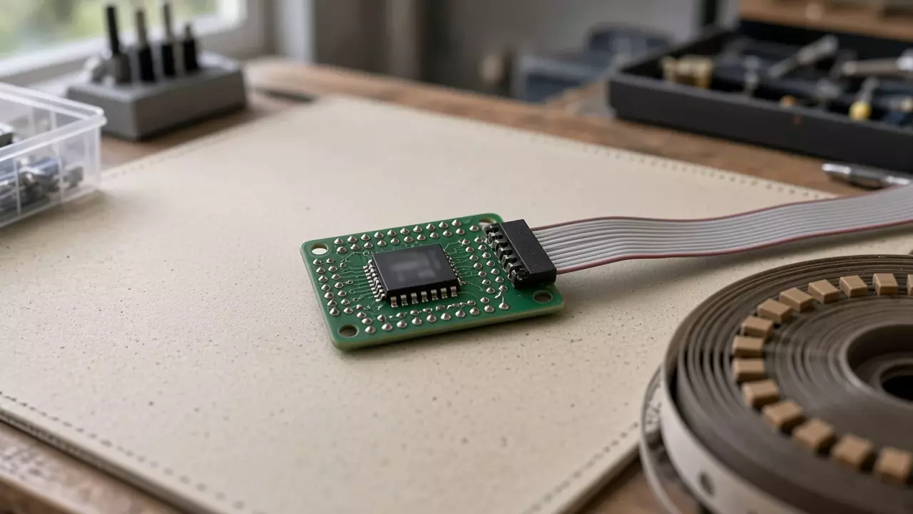
A gray ribbon cable plugged into a header on an unlabeled green board.
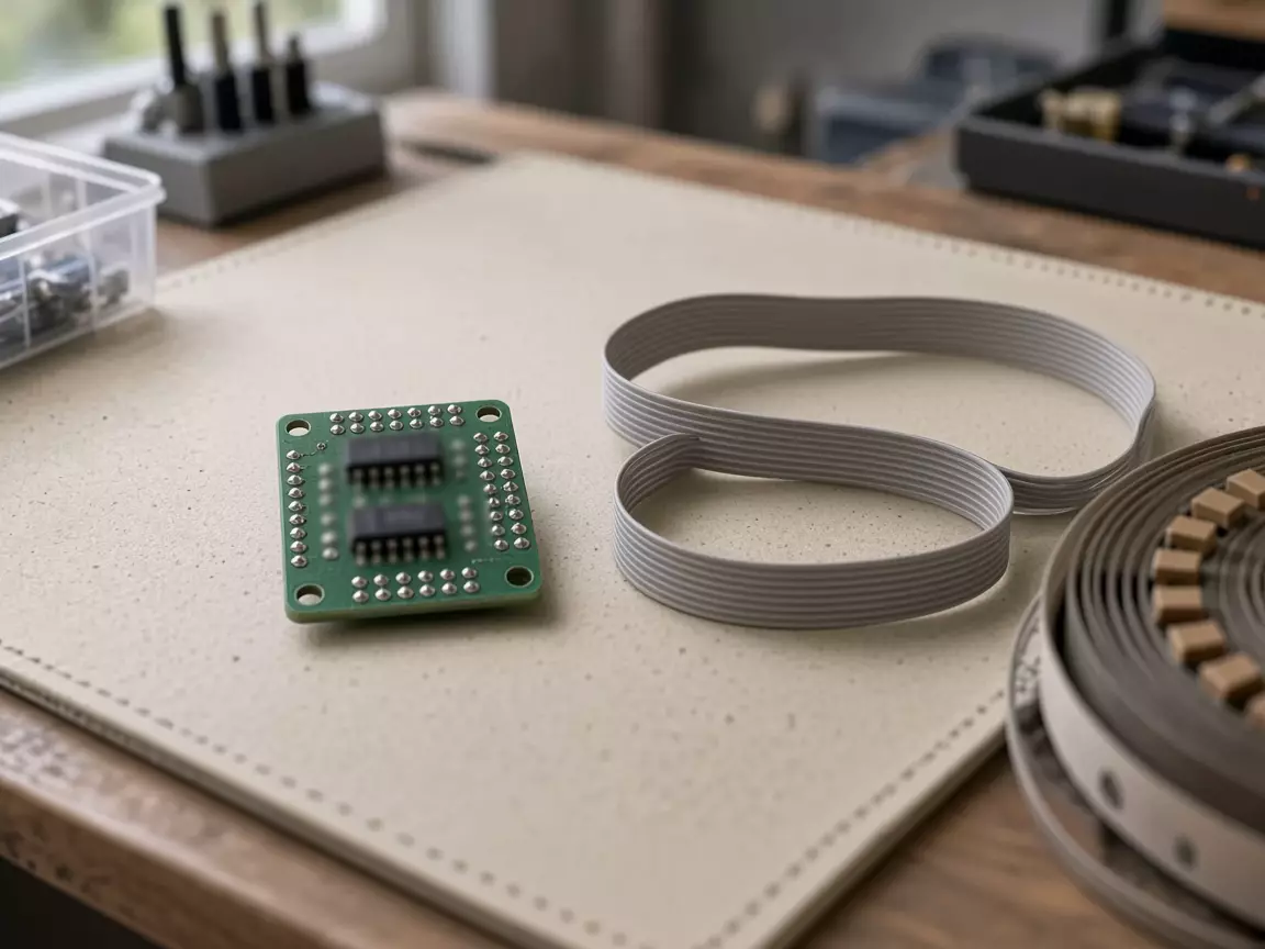
An unlabeled green board beside a coiled gray ribbon cable that is not plugged in.
The JTAG and SWD header checklist is the pin record for that connector. It does not read reset flags. This page does not choose TDI, TDO, SWDIO, or SWCLK.
Common mistake: Treating a breakpoint on the refresh line as proof the watchdog was fed in free run. Pain’s 4 December 2020 note says the breakpoint was hit, and the counters around the feed both incremented, while the independent watchdog still reset his STM32F4 once the scheduler was running.
Takeaway: Accept an IWDG reset only when the saved flag says so after a no-refresh spin with the probe disconnected.
Why can a feed the debugger hits still miss?
Pain’s report is one STM32F4, CubeMX, FreeRTOS v10.2.1, CMSIS-RTOS V1.02. He wrote that the watchdog reset if it was not fed every 512 ms. The feed lived in its own task at osPriorityRealTime. Other tasks were osPriorityNormal. configTICK_RATE_HZ was 1000, preemption was on, and he had moved the CubeMX timebase from SysTick to TIM7. He confirmed the independent watchdog from RCC->CSR. He did not paste a flag name.
Before osKernelStart, a loop that fed the watchdog ran, and a loop that did not feed it reset on that same half-second pattern. After the scheduler started, both IWDG->KR = 0xAAAA and HAL_IWDG_Refresh failed to hold the part, including with interrupts disabled around the feed. The debugger stopped on the feed line. Variables incremented on both sides of that line. None of that, in his account, stopped the resets.
Richard Barry asked whether IWDG->KR = 0xAAAA was the only instruction required, and whether the task could still reach that address after the scheduler started. His example was a memory-protection unit that blocks the access. The thread does not show that an MPU was enabled on Pain’s board. Record it only if your map shows it.
On 14 December 2020 Pain wrote that a normal-priority STemWin task appeared to make the realtime feed miss a cycle. uxTaskGetStackHighWaterMark stayed under half the stack. He lowered the graphics task to osPriorityBelowNormal, which he said matched the emWin guidance, and the resets stopped. He called that a hack. Hartmut Schaefer replied that he uses watchdog timeouts of a couple of seconds, as a last resort on fatal errors, and that 512 ms is tight when flash erase or programming stalls execution from single-bank flash regardless of priority. He described that stall as N times 100 ms. That is his description, not a sector time from a datasheet.
Gaurav Aggarwal posted a different part in the same thread, an STM32H7, with IWDG_PRESCALER_4, window 4095, reload 4095, and HAL_IWDG_Refresh followed by osDelay(10). Those fields are his H7 init. They are not a replacement for Pain’s 512 ms, and they are not a value to drop into an F4 project.
Takeaway: A breakpoint on the feed, and a realtime priority, did not settle Pain’s F4. Write the blocking call, and copy the timeout from the manual, before you change task priorities.
When does a flash erase reset the part before the interrupt runs?
franz2399 wrote on 22 February 2012 that FLASH_EraseSector on an STM32F205RCT6, on an STM320G-EVAL, took longer than his watchdog timeout, and that WWDG_IRQHandler was not called during the erase. He quoted a reference manual line: when the early-wakeup interrupt cannot be served, for example because of a system lock in a higher-priority task, the window-watchdog reset is eventually generated. He also quoted the line that a watchdog cannot be disabled again except by a reset.
The next day he quoted two documents this page has not opened. From a datasheet table he cited, erase time for a 128 KB sector was more than 1 second. From a reference-manual section he cited, at 30 MHz (fPCLK1) and prescaler 8, the maximum watchdog timeout was 69.91 ms. Those two figures are what he said the documents printed. They stay with the F205 and with the documents he named. They do not fill the timeout cell for another MCU.
Tesla DeLorean’s replies on 23 February 2012 separate the clocks and the stall. He wrote that the IWDG comes from a low-frequency source and the WWDG comes from APB1 divided by 4096. He wrote that he had looked at the manual and that F2 and F4 do not clock the WWDG from the LSI: the prescale is 1, 2, 4, or 8. He also wrote that code which executes from the flash array stalls until the erase or program finishes, and that the practical alternatives he named were to run the critical code from RAM, or to erase before the watchdog is enabled. emalund’s suggestion to clock “the puppy” from the LSI matches the IWDG in Tesla’s account, not the WWDG on F2 and F4.
A 20 second refresh does not answer a window watchdog that resets at the enable write. On 18 March 2025 emirhan37’s STM32F767 reset inside HAL_WWDG_Init, on WRITE_REG of CR with WWDG_CR_WDGA and the counter, before the prescaler and window were written to CFR. He posted prescaler 8, window 64, counter 127, early-wakeup interrupt disabled, and APB1 at 54 MHz, which he called the maximum. He had a timer set to refresh every 20 seconds. TDK replied that, unlike the IWDG, the WWDG has to be refreshed inside a window, and that a refresh outside that window resets the part. TDK said the posted code looked fine. The saved page ends at “Show 3 more replies.” This page does not invent the missing replies, and it does not turn 54 MHz into a timeout.
The L476 wiki’s WWDG example range, 51.2 µs to 28.2 ms, shows why a 20 second period is outside that example. It does not say what the maximum window is on an F767. Leave that cell blank until the F7 reference manual is open.
Takeaway: Record the erase, or the init write, that blocks the feed. Quote the timeout from the manual for that part. Do not stretch a window watchdog to outlast a flash sector by editing a number from a different series.
When this log does not settle the reset
- The reference manual for this part is closed. Pavel’s three flag names, the wiki’s 0xAAAA key, and every L476 time on this page stay in the source column. The log stays blank.
- The window option is unknown. The January 2023 question was about the window option disabled. The L476 IWDG demo sets the window equal to the reload. Write which one your init uses. Do not assume disabled.
- The reset is the software-reset flag in Pavel’s third branch. That branch is NVIC_SystemReset or the debugger. It is not an IWDG result.
- The counter is frozen while the probe is attached. Repeat the spin with the probe disconnected. The wiki states that freeze is possible. It does not name the debug bit on this page, so the freeze cell stays blank until your manual names it.
- Flash erase or a long program is the blocker. Tesla’s 2012 replies point at running from RAM, or erasing before the watchdog starts. Lengthening the timeout, or disabling the watchdog, is not the check this page is for.
- The part is not an STM32, or the watchdog is an external chip. The saved pages used here do not cover that case.
- You need a safety-certification claim. emalund mentioned certifications that want a separate watchdog clock. This page does not say any part meets one.
Takeaway: Stop when the manual, the saved flag, or the probe-off spin is missing. A longer timeout is not a substitute for the missing cell.
Method and sources
Compiled on 14 October 2026 from five public pages fetched on 11 October 2026. Each returned a saved body. No STM32 was flashed, and no reset was counted, for this article.
The ST Community thread opened by mm.51 on 4 January 2023 names the board as Nucleo-L476RG and the IDE as STM32CubeIDE 1.11.0. MM..1’s one-line note is dated 4 January 2023. Pavel A.’s reply, marked Best answer, is dated 5 January 2023 and is the source of the three flag tests. The six-step key sequence in the question is quoted there as configuration text. It is not re-checked here against a reference manual.
The wiki page is the copy marked approved at 13:43 on 4 September 2026 and retrieved as oldid 90007. The L476 ranges, the NUCLEO-L476RG demos, the 250 Hz and 400 ms arithmetic, the 20 ms comment, the 0xFFF start value, the 0xAAAA key, and the freeze-in-debug sentences are taken from that copy. The page tells the reader to use the IWDG chapter in the product reference manual for anything beyond it.
The FreeRTOS thread is Pain’s posts on 4 and 14 December 2020, Richard Barry and Hartmut Schaefer on 4 December, Gaurav Aggarwal’s H7 snippet on 4 December, and Hartmut’s flash-stall note on 14 December. The 512 ms figure, the half-second resets, and the stack high-water remark are Pain’s report about his F4. The H7 prescaler, window, and reload are Gaurav’s.
The flash thread is the February 2012 exchange on STM32F205RCT6. The “more than 1 second” erase line and the 69.91 ms line are franz2399’s quotations from documents this page did not open. Tesla’s APB1/4096 and LSI statements are what he wrote after saying he had looked at the manual.
The F767 thread is emirhan37 and TDK on 18 March 2025. The saved copy includes the init function and the posted configuration. It stops before the replies hidden under “Show 3 more replies.”
Related reading
- JTAG and SWD header checklist: which debug pins the connector still needs. It does not read reset flags.
- Embedded Systems: other notes filed in this category.
- Article index: the list this log sits on.